 Forgive this messy rant….
After obsessing over CNC machines for about 10 years, and having some misadventures from time to time designing my own hardware and software, I jumped at the chance to order the original Shapeoko CNC mill mechanical kit as soon as it came out. It took me a year to find time to put it all together. After it was assembled, I connected up my old HobbyCNCPro Motor driver board to it. This driver board is for Unipolar motors, so I searched for some that would work. I found these NEMA 17s from pololu <<LINK>>
On a previous attempt at making a CNC machine, I used Mach 3, but this time I went with LinuxCNC. The main reason I wanted the machine was to mill PCBs. The workflow was EaglecAD–>pcb-Gcode–>autoleveller–>linuxCNC.<<LINK>> I made a few really horrible PCBs with the machine before realizing it simply wasn’t the tool for the job. The gantry had way too much play. The eShapeoko community was constantly updating and improving on the designs, so I waited it out until the V2 came out before the obsession hit me again when I saw how they doubled the gantry slides to improve strength.
After a year of V2 being on the market, I searched forums for a conversion pack but none was to be found. So I spent a while trying to define the differences between the machines. In the end, I spent probably just as much as buying a whole new mechanical kit, but here’s my process.
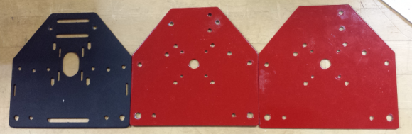
First, instead of buying all new motor mount plates, I only bought 2. I then modified a couple of my plates from my original machine. IN the image below, you can see the original plate on the right, the new plate on the left, and the modified one in the middle. I basically just had someone with a drill press line up the new plate with the old and drill out a two holes at the top that could attach the 70mm machine screws through to make the carriage assembly (pictured further down.)
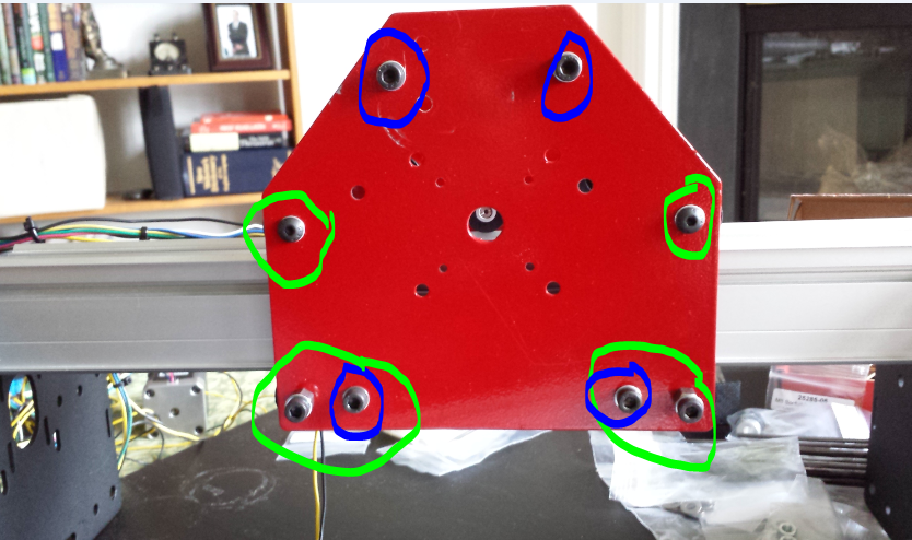
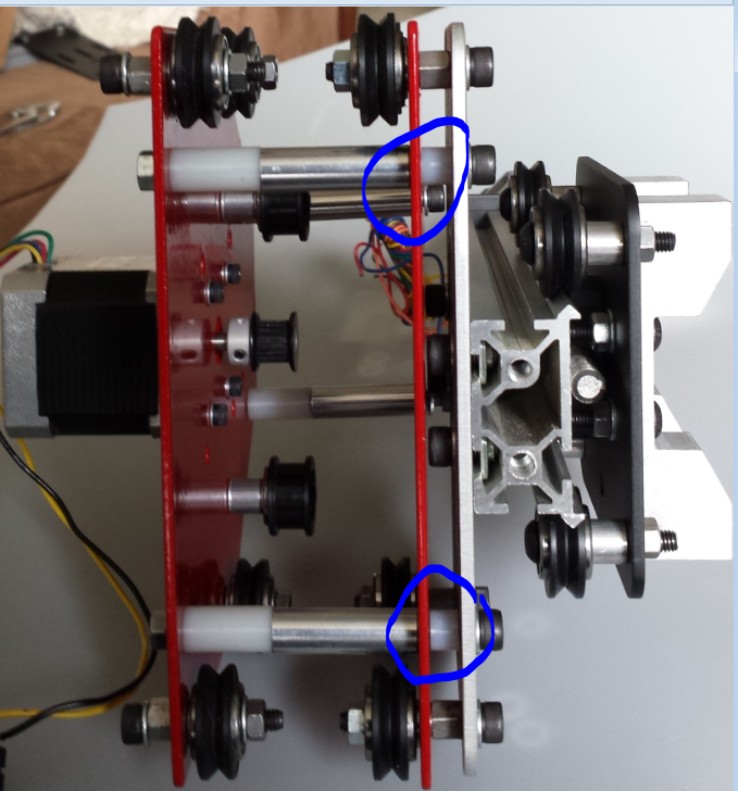
The V1 Y rails became my new gantry, leaving me with something like 375mm in that dimension. After I mounted the carriage assembly, I saw that the Z axis had no holes to mount to. To remedy this, I simply used the V1 Z plate as an interface between the new Z axis and the carriage. In the image below, you can see the bolts I had to extend with short nylon spacers so they could mount the old Z plate and line up with the original eccentric nut circled in green while the four 70mm long spacer screws are circled in blue. (I had to buy 4 70mm M5 bolts on amazon as inventabes doesn’t sell them for some reason).
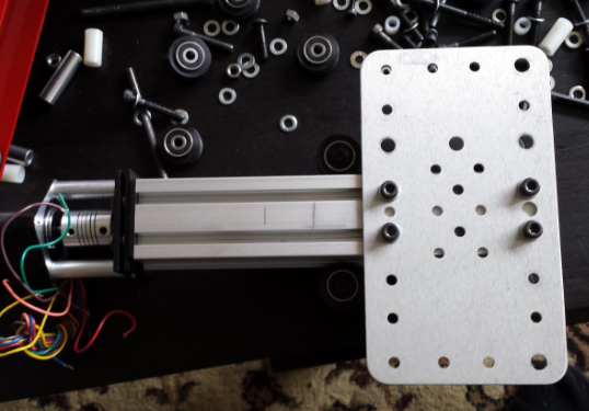
Below you can see the spacers and everything inside the carriage assembly. This is a “bottom-up” view after the Z axis has been mounted.
I was able to use the belt and the belt standoffs from my V1 on the gantry with no problem, but the lower profile of the new motor mount plates that became my new Y axis required the belt to be clipped to the slide itself. Instead of buying them, I just laid my V1 standoffs for the belt flat and mounted them that way. This reduced cutting area, but the first thing I will cut will be smaller belt clips.
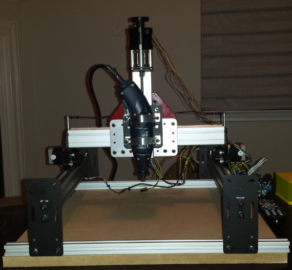
I ordered a 1000mm piece of Makerslide and cut it directly in half, leaving me with about 500mm rails. I mounted these up with new end mount plates and some 80 X 20 aluminum. I was disappointed to see that I couldn’t use readily available half-inch MDF as spoilboard on top of the extrusion, so I just mounted the entire machine on a 500mm X 500mm piece of half-inch MDF. This gives me a bit more Z depth.
I was not very excited when I saw that my cutting area is less now than it was with the V1. I’m contemplating ordering more makerslide if I need to in the future.
Another change I made was to get a unipolar stepper with the shaft sticking out of the back for my z axis, and used a 3d printer to print a thumbwheel to attach to it. Now I don’t have to struggle to adjust the Z axis by hand anymore. I hadn’t used this company before, but <<LINK HERE> stepper world? was cheap, shipped fast and packaged everything great. The only problem I found with the datasheet they included is that they had labeled the brown wire “BLW” for some reason.
If I can find another NEMA23 aound the house, I will replace my Y axis motors with NEMA23s for added power.
I’m also hacking on the electronics. I added the 4th axis motor driver to the HobbyCNC Pro board and would like to use it to drive a 3d printer extruder. Since the HobbyCNC Pro board interfaces with a parallel port, it isn’t very practical for my laptop, so I decided to slap an arduino on there running GRBL to simplify the entire process. After seeing a demonstration of chillipeppr for GRBL, I’m thinking of using that. I kind of dig the browser-based tools available for controlling the machine for their simplicity.I don’t wanna use my PhD to make PCBs I just want to click a button and be done with it. It shouldn’t be such a pill to make things on the CNC. For using GRBL with 4 axes, I’m looking at using the spindle speed control as my extruder, or using a slave ATmega328, or even just getting the timing set for strapping my 3doodler onto the thing. The interfacing of the driver and the arduino should be pretty straightforward, I just need to wire X direction on one to X direction on the other, etc. for the most part.
My tool tip wobbles as the Z goes up and down, which sounds to me like I have a bent leadscrew somehow. I’ not sure about this and will have to hack on it later.
Anyway, that’s my progress so far. Any more info and I’ll post it when I get the chance.

Hi Adam,
I inherited a Shapeoko 1 and was looking at possible upgrades to a 2.
I liked your comments on the experience and was curious why you couldn’t use
the MDF spoilboard on top of the aluminum extrusion. Is there not enough Z clearance?
(I was hoping to be able to use the 500mm x 500mm board and clamp system from Instructables)
thanks.
You can do that but it will eat up some of your z height. You can home their Z off the extruded aluminum and then enter your material high as an offset to make sure you never touch the excursions. Here’s a video that does a great job explaining the process. It should work with any software. I suggest you test it first by running a few jobs on MDF to test it. Also this assumes your workspace is completely level, so sound time to level it. Another thing if yucky can’t level it for done reason is to do what done 3d printers are doing now and using a z probe to measure several spots on the work area, then it modifies the gcode live to adjust for height changes. Check out the printrbot models that do this, it’s pretty cool and created some beautiful print results.
thanks for the tips;
I have a printrbot simple metal with the induction Z-probe;
that’s another project in the pipe: adding a second extruder!
-d