The first step in this was to find out when something is plugged in. I tried all sorts of things with windows event viewer to see if I could detect this because I didn’t want to have yet another service running in the background on my PC eating resources all the time, and I wanted the reaction to be fast, so polling every 10 seconds or something would be too long to wait for a popup. Alas, I couldn’t find any way to get USB port data to trigger an event in windows when you plug in a USB port.
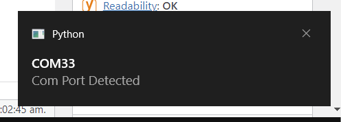
Looking online for examples I only seemed to find C# or VS code. I’m not installing anything more to develop this one project, and at first I wanted to see if there was a cross-platform solution since I was going to have to write it all from scratch. Eventually I settled on a windows-only solution because I found an excellent site that is full of good code examples for win32 python interfacing from a user’s post on stackoverflow. these kinds of sites are few and far between, so I’m glad I came across it! This code example connects into Windows Notification center and WMI (Windows Management Interface) to detect when USB items are plugged in. You can detect drives, networking, and serial ports based on the example in the link.
When you run python code, by default, the command window is always visible, so I tried a few things to hide it. Firstly, you should be able to just use pythonw.exe instead of python to run the code and it should hide the window. For some reason, this didn’t always work. The next thing I tried was using the win32 library in python. This grabs the foreground window and hides it. Since the foreground window is likely this python script, it works fine. Running it sometimes takes a faction of a second for it to hide the window so sometimes you see it flash a command window.
The final step is to have this app start when you turn on the computer. Some folks said you could just put your python file into the windows startup folder, but this never worked for me. Instead, I keep the python script in my installations folder (where I keep all my useful apps) and I wrote a batch script to run the python code. I saved the batch script into my startup folder and rebooted. It works great and doesn’t use many resources at all!
Now, if you use linux or mac, I recommend you check out usb-ser-mon which has some of the same functionality of detecting plugged-in devices. Then you can use the same plyer code to generate a popup from what I understand.
The goal is to generate wood grain patterns for laser cutting/CNC of plywood. Mainly, I wanted to have something similar to spalted maple laser etched onto the plain birch veneered plywood. The thing that inspired this project was this post of speaker boxes on imgur I came across. The design looked really cool, and while spalted maple is expensive, birch plywood is relatively cheap.
My first step was to procedurally create a random pattern. Similar to the imgur post, I looked at creating camouflage. I found a great example code on openprocessing by ThingOnItsOwn that used perlin noise to create a camouflage pattern. I tweaked the values a bit experimentally, then stretched the entire design to make the final design look more like woodgrain.
The next step was to just capture the edges of these blob shapes from the first pattern. I came across this example from Richard Bourne It is forked from this example from R. Luke DuBois. Honestly I was being lazy because I had written edge detection code in college as it is standard image processing, but I knew someone else had it already in processing. Instead of using for loops, this version manually calculates out the kernel.
This leaves me with a result that looks pretty realistic.
Camo:
Spalting:
This creates a PNG filetype which can be used to add texture to a 3D print in the slicer. The slicer will adjust the print to incorporate the texture in 3D giving it a woodgrain-like effect. You technically could use this as-is on a laser cutter to create spalting like my inspiration, however being raster data, it would take the laser a long time. It’d have to scan the laser (the thickness of a human hair) across the entire area of the panel you are applying the texture on. To make this faster, you can vectorize the PNG in inkscape or other software to outline the dark areas of the PNG. This will cut fast as it is a vector (the laser would just have to draw the lines the same way your hand would. That would save a lot of time.
If anyone wants to add vectorizing to my code, please do! You can clone my github and put it on P5.js. I was going to add it, but I got lazy again. I even asked ChatGPT3 to help combine this code with something like potrace or imagetracerjs but it produced code that looked great, some even compiled after a few tweaks, but never worked.
So I was at the bin store the other day and I came across a couple of Baofeng TP-8Plus radios. I’m no expert on HAM radios in general (please correct me on anything I’m wrong about on this page BTW), but I got these two for $7 each so I couldn’t beat it. It turns out, the models I picked up are now a ubiquitous hardware model with different firmware which can be used for multiple purposes.
Firstly, I can’t tell the differences, but the TP-8Plus is apparently also called the UV-13 Pro.. as well as many other models (listed below). There are different levels when talking about radios like this, HAM and GMRS. HAM radio is amateur radio and you have to pass certifications tests for the license. These radios are classified as HAM radios since their broadcast power is too high for GMRS (which is a higher powered two-way walkie-talkie band). To use GMRS band, you need a radio rated for this band and a GMRS license (no certification test required) and your whole family can use the radios apparently. The radios are too powerful as they are for this, however there’s a firmware you can get for them that limits the broadcasting power turning them into GMRS-legal radios (from what I have read..)
Where to get Firmware:
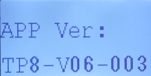
Before doing anything, I took a pic of the current firmware version as shown below. You can see this by holding the flashlight button as you turn on the radio
I was unable to figure out how to copy this ROM onto my PC, but I did find an older version of the UV-13 firmware I could use to replace it if I needed to… which I did. I wish I could find the firmware online.
Where do you get firmware? It depends on what you want your radio to do. I have it on the authority of some random dude on reddit and other that this radio’s hardware “is the same for Baofeng UV-13, TP-8, Explorer QRZ-1, TYT TH-UV88, Pofung P15UV, Rugged GMR2, TIDRADIO TD-H5, Retevis RT85, and Radioddity MU-5, GM-30.” Firmware for those radios should work here. They each have slightly different abilities, so it is really up to you. what you’d like it to do. Do your research to see what legal licensing steps you can take based on how you want to use your radios. Comment below if you know where to find other firmware for this radio.
For using this as a HAM radio (where you can enter in frequencies manually or scan them in the 2m band) the UV-13 firmware was easiest to find. The only version I came across online from multiple sources was UV13-Firmware-V06.01.013-20211104_01013.bin I was able to successfully install this without issue and I can still write program settings using the P15-UV software.
For GMRS walkie-talkie usage, I came across the Radioddity page with their firmware. It is important to note that after installing this firmware, I had to use Radioddity’s own version of P15-UV branded “GM-30”. The link to their firmware and programming app is here. From what I read, this firmware limits the transmit frequency making it legal to use the radio. NOTE: I am not a lawyer and I have no way to test the radio’s power with this firmware to compare, it is just what I read on the internet.
Programming:
There are 2 programming modes. One for just reading/writing programmed channels and settings, and another mode for updating firmware. There’s a trick to program firmware I describe below.
I already had a USB cable for these radios since I had an older model. Once installed you can plug it up to the radio, turn on the radio and connect. In the PUV-15 software, select “Program–>Communication Port” and select the com port. If you don’t know which this is, open windows device manager and look for the COM port that disappears when you unplug the cable.
Next you want to back up and save all the channels and settings from the radio by selecting “Program–>Read from Radio” and click “OK” to read all the default settings. Then you have to click “File–>Save As.” This will save your channels and any program settings to a file on your computer.
To flash the firmware, download your preferred firmware version (more on this below) and select “Program–>Tool” For this to work you must manually put the radio in programming mode by turning it off, holding down the PTT and Flashlight button as you turn it back on again. You know you did this right when the screen does NOT come on, but the red light at the top glows dimly.
Click “Upgrade” button on the app to change the firmware. DO NOT INTERRUPT THIS PROCESS or you might brick the device.
Rewrite the channels and program settings by choosing “Program–>Write to Radio”
If you were a genius like me and forgot to backup your settings, your menus and voice might now be Chinese. No problem, simply change the language by scrolling through the menu that says this:
Then pressing the menu button to edit and the down button to change it to English. Press menu again to confirm the change.
Licensing:
Again, I am no expert on the matter, but here’s what I learned from all the forum posts and videos I found on this radio. There is no license required to use these radios as listening-only devices. You can use them as weather radios or even emergency service scanners. If you wish to transmit at all you’ll need either a GMRS license or a HAM radio license depending on what firmware you have and how you plan to use the radio. See the comparison chart below:
GMRS
HAM
One license covers your family. Licensing process is confusing, so watch a recent tutorial video on the process to find out the steps required.
One license covers you. You can allow your family to broadcast, but you must be there with them at the time.
No exam required
Must pass a certification exam (there are different levels)
To be used as walkie-talkies (eg. in your family) because they are shorter-range transmissions.
Connect with community of HAM radio operators all over the country, world, and even on the international space station!
This post is a not on a lot of techniques for using different types of machines and processes for making stuff. I’ve had this for years but decided to finally publish it. I’ll add to it periodically, but I figured others might find it useful as well. RIGHT-CLICK to open in new windows.
Understand the basics of program flow before learning code. Flowgorithm is a tool that is really helpful for learning that. Tinkercad Circuits is great as it has MakeBlock (or something like it) built into it.
Get a nice silkscreen on the top of your boards by simply using the toner transfer method of the board’s silkscreen layer.
Using a vinyl cutter, you can cut a soldermask from kapton tape . This method is great because it’s temperature stable for soldering and see-though so you can follow traces during debugging. You might be able to use a laser for cutting the tape, but the vinyl cutter is preferred
Interactive continuous fabrication. This uses tracking of a designers hand and a robot arm and a blow moulding technique to fabricate objects out of sheet material. (Interesting research)
CurveBoards, breadboards built into 3D printed objects. (Interesting research)
Photo-Chromatic inks used to “repaint” objects with different designs using light (Interesting research)
I recently taught a class utilizing PIC chips and MPlabx. This is the first time I used PIC chips in about 20 years. I have to say, it has been one of the most frustrating experiences I have had programming chips in a very long time. MPlabx is a modified version of Netbeans, with which I am intimately familiar with as I used it for my graduate work. My class had an impossibly hard time consistently programming chips. This page documents some of the ways we fixed the problem.
While coding, sometimes, seemingly randomly, MPLabx will start throwing underlining things and start throwing errors such as “TRISA no defined.” It is as if the link to the libraries gets severed. I have no clue why this happens, but two things seem to fix it. 1. Save the file you are editing because sometimes it is just that the changes you’ve made have not been saved and it can’t find some of the declarations for things. 2. When the problem persists or actually won’t compile, then you have to Restart MPlabx. Once it loads up again, it will re-register all the library paths and all is well. If this doesn’t fix the problem, then check the errors and make sure you have the correct number of curly bracket “}” and in the right places. Remember, no executable code can exist outside of functions except global declarations.
Programming issues:
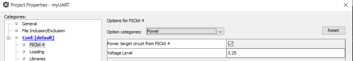
One of the biggest issues was powering the circuit. By default, every project expects your circuit to be powered externally. The programmer even has a pin dedicated to sensing this voltage and stopping everything if it isn’t sensed. You have 2 options. Either power the circuit externally, or you can go to project properties, Conf–>PIckit4 (or whatever programmer you have) and select “power” from the dropdown and checking to power the board. Check the box next to “Power target from…”
This will only work if your circuit is low-powered. If you need a significant amount of power, then you must power the board separately and make sure this setting is NOT checked. Sometimes this can prevent the chip from programming, but more on this later.
Programming Pins:
The programmers only have a few pins that are used on the processor, but those are very important.
Memclr/Reset: This pin basically tells the processor it is being reprogrammed. (There’s more to it, but out of the scope of this post).
Target voltage: This senses whether or not the processor has power. If not, then the programmer won’t attempt to talk to it and will instead error out.
PGD: Programmer data. This is often on a standard port pin, so if programming keeps failing, isolate this pin form anything else. ie. remove all externally connected things like buttons, LEDs, whatever else you might have connected to this pin and only connect the programmer.
PGC: Programmer clock. The same applies from above.
Gnd: Communication required a shared ground so make sure this is connected correctly.
If the PGD, PGC, and GND are not connected correctly, you’ll often get the following type of error:
Target Device ID (0x0) is an Invalid Device ID. Please check your connections to the Target Device.
Each processor has a special register that contains a number identifying what type of chip it is. The programmer requests this info before programming so it won’t accidently brick the chip by writing to it in the wrong places. The device ID is NEVER 0x0 for any processor. If you see this error that means that the programmer was unable to get a correct value from the PGD pin. Check your connections for shorts, opens, and remove any circuitry attached to the programming pins except the programmer itself.
Otherwise, you might get something like the following:
Target Device ID (0x6750000) is an Invalid Device ID. Please check your connections to the Target Device.
This error shows that a value number was returned, however this doesn’t match the chip your project is set to compile for. Check your program properties and make sure the chip number matches the part number labeled on the processor itself.
Programmer Quality:
While not do or die, I will say that a good programmer is helpful. Don’t get me wrong, I’ve cobbled together some super janky programmers back in the day that have worked, but having a quality device certainly helps troubleshoot. We originally started using PICkit3 programmer (without the Microchip logo, which I think indicates they are clones). For about 2 weeks, while it worked about 80% of the time on my laptop, having a class of laptops with different configurations ,etc. led us to have such problems that I searched for other solutions. The first thing that helped was to use the MicrostickII and solder up a converter board that converted the programming pinout to a programing cable. This solved the problem for a few students.
Eventually I was approved to buy official PICkit4 programmers, which seemed to help even more. However unexpectedly and randomly, some folks still had a warning pop up suddenly, after successfully programming multiple times in a row, which prevented them from having success. There would be absolutely no hardware or settings changes, only small tweaks to the code, but suddenly the chips would refuse programming.
Though there were multiple error, the most common was
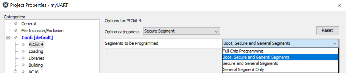
Programming did not complete. You are trying to change protected boot memory. In order to do this you must select the “Boot, Secure and General Segments” option on the debug tool Secure Segment properties page.
Attempt 1 (rarely successful): Some folks online suggested manually erasing the chip first, then trying to program. This rarely works.
Attempt 2 (sometimes successful): Maybe your circuit requires more power than your programmer or USB can provide. Go in the settings as described above and uncheck “Power target circuit…” and make sure to provide an external power source.
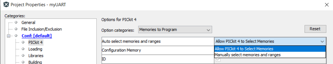
Attempt 3 (sometimes successful): Again, this is after multiple successful attempts and no hardware or program setting changes. My predecessor told me that when this happens, the fix is typically to do the following: Open the project properties, Select Conf–>PicKit4 (or whatever programmer you have) then select “Memories” from the dropdown and change it from “Automatic” to “Manual” then click “Apply” Then click it back to “Automatic” and apply then click OK. This seems to work sometimes…
Attempt 3 (the actual fix): Well, I could have just read the error message because it tells you just what to do… kind of. Open project properties: –>Conf->PICkit4 then from the dropdown, select “Secure Segment” and change the “Segments to be programmed” to “Boot, Secure and General Segments”
Why is this not default? Why does it work multiple times, then suddenly require this change? Who knows? I would absolutely love an explanation for this behavior.
After successfully programming for a n hour or so, a new error I inexplicably received suddenly appears as follows:
Erasing… [config mem] 0xf80000, expected 0xcf, got 0x0. You have set the program speed to Normal. The circuit on your board may require you to slow the speed down. Please change the setting in the tool properties to low and try the operation again. Programming did not complete.
Changing programing speeds does nothing:
Erasing…
[config mem] 0xf80000, expected 0xcf, got 0x0. Programming did not complete.
If you run into this, disconnect power to your chip and programmer, and plug it all back in. Sometimes this requires you just unplug your programmer from USB and replug the programmer to your computer. Again, this happens when I’ve been successfully programming for an hour or so, literally nothing changes except tweaks to my code, and suddenly nothing wants to work. No explanation for as to why this happens.