I finally got a chance to play with the SAMD11C chips FabAcademy has been recommending for a while. I also wanted to learn to use KiCAD a bit more so I made a multi-use board with the SAMD11C which can be used for UART, UPDI programmer, and as a FreeDAP board. You can find all of my files for this project, including the firmware at my FabAcademy gitlab page.
I will be making a modification of the board Quentin designed.
Right click anywhere on the screen and select “program” then “open server program” and search for Roland→SRM-20 → PCB png. To use any other CNC (Shapeoko, Xcarve, 3018, etc.) you can select G-code→ mill 2D PCB png. This will accept in a PNG image file and generate the cut file you will send to your machine.
Then we’ll modify this to save a file for us.
If your X, Y, and Z, look like the GIF above, you’ll do an “air cut”. An “air cut” is a test that runs the same code, just offset in the Z axis (and this case X and Y as well) just to make sure everything will cut as you would expect. Then you’ll regenerate your cut file by changing the X, Y and Z defaults to 0s in mods before exporting your cutfile again.
Once the board is cut, it must be populated… Break out the old iron and solder up the design. If you don’t have a switch like the one I used, you can simply install some male headers and use a jumper to select the voltage. The SAMD doesn’t have a lot of external accessories which makes this part a good bit easier than say some of the older FabISP designs.
Once populated, the board needs to have firmware flashed to it. For this step, I will use the Atmel ICE programmer and a windows computer.
First download windows version of edbg which is the debugger tool we’ll use to download the firmware.
Then download the binary of the firmware. I am using the SAMD11C arduino bootloader core firmware so I can use the chip with the Arduino IDE and libraries. (This bootloader seems to eat up a good bit of memory, even on these ARM devices).
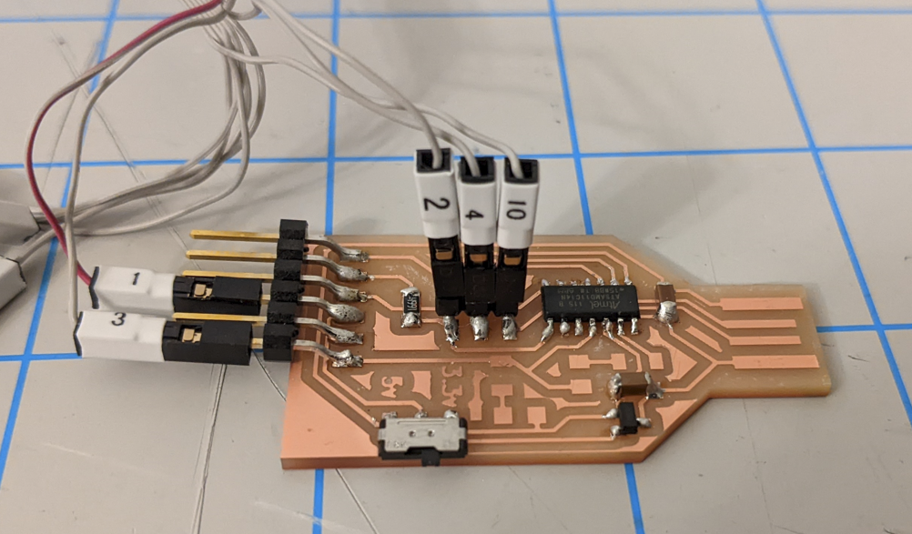
Connect up the atmel ICE programmer to the SAMD board. I used figure 3-8 from the atmel ice manual to figure out the pinout because we are using the Serial-Wire debug (SWD) pinout.
Above you can see the specific pins for programming the firmware with the Atmel ICE. Pin 1 is Target Voltage (Vcc), pin 2 is SWDIO, pin 3 is GND, and pin 4 is SWDCLK. Pin 10 is the Reset.
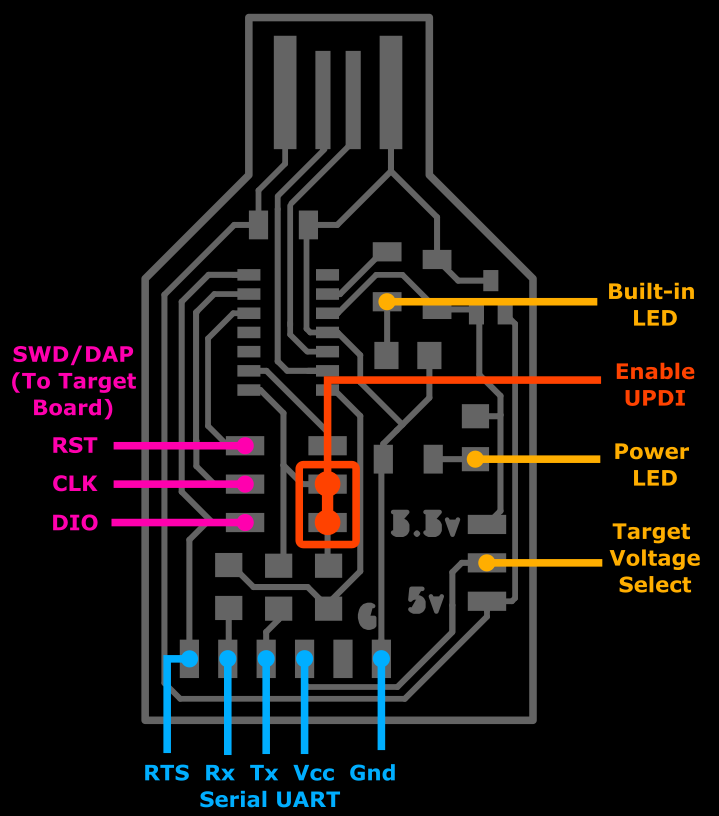
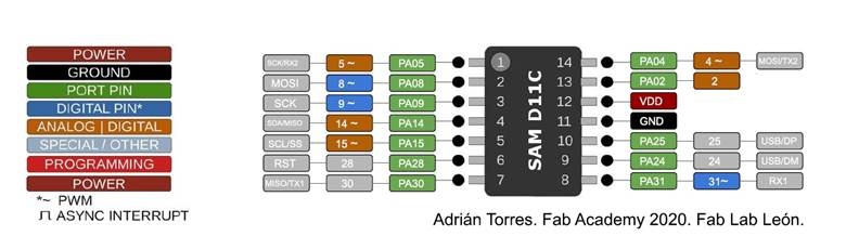
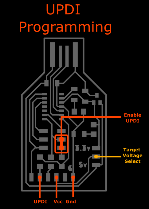
Here are the pins and usage of the board:
Finally you’ll need to open the command prompt in windows, cd to the directory you downloaded these files to and run the following command (assuming you went with the 2nd firmware option above):
Then you need to install the SAMD boards. In Arduino go to Tools→Boards→Board manager
Search for “SAMD” and install the “MattairTech” one only.
Once this is installed (it will take a bit of time) We can write some arduino code to run on our new board. Let’s start with a blinky program. Looking at the pinout of the SAMD11C, we can choose a pin to connect an LED to on a breadboard.
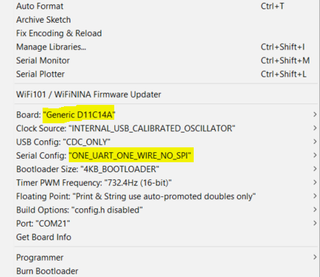
You better make sure that you always use “INTERNAL_USB_CALIBRATED_OSCILLATOR” when you plan to keep this plugged into the USB port for power, or “INTERNAL_OSCILLATOR” when you want tit to be standalone. If you select the other two options, you’ll have to reprogram the firmware with the ICE or a DAP. It basically bricks the chip if you tell it to use an external crystal but don’t add a xtal to your design.
Arduino file to be serial print to test. The pinout is simple. Each output uses the same pin number as the SAMD chip output. This is unlike a normal Arduino.
You can download this code to test your board (whether you have a working LED or not). Once this uploads, open the serial terminal and you should see “hello”
void setup() {
   SerialUSB.begin(0);
}

void loop() {
      SerialUSB.println("hello"); //Send stuff from USB to serial port
} //end loop
If you want to test to make sure that your board can now be programmed from the Arduino IDE, you can flash the built-in LED on pin 2 with this code:
int led = 2;

// the setup routine runs once when you press reset:
void setup() {
  // initialize the digital pin as an output.
  pinMode(led, OUTPUT);
}

void loop() {
  digitalWrite(led, HIGH);   // turn the LED on (HIGH is the voltage level)
  delay(1000);               // wait for a second
  digitalWrite(led, LOW);    // turn the LED off by making the voltage LOW
  delay(1000);               // wait for a second
}
The following Arduino file makes this board into a UPDI programmer when you add a jumper to the appropriate pins (see above). Simply take data from the USB serial port and put it on the output serial port and vice versa.
void setup() {

   SerialUSB.begin(0);
   Serial1.begin(57600, SERIAL_8E2); //Adjust baud rate and use SERIAL_8N1 for regular serial port usage
}

void loop() {
   if (SerialUSB.available()) {
      Serial1.write((char) SerialUSB.read()); //Send stuff from Serial port to USB
   }
   if (Serial1.available()) {
      SerialUSB.write((char) Serial1.read()); //Send stuff from USB to serial port
   }
} //end loop
Program a target board over UPDI:
Once you have downloaded the above serial code to your board, you can use it to program attiny412 or attiny1614 chips over UPDI.
Get the code from that link to blink the LED on pin 0.
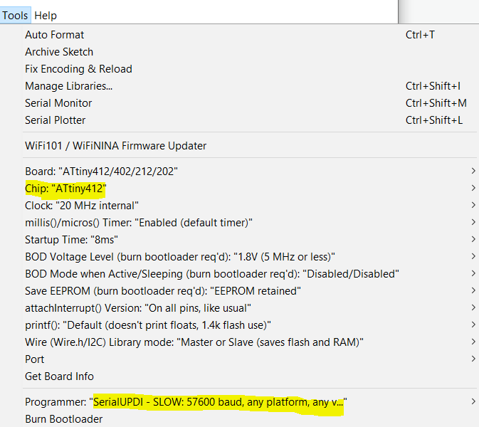
Most important part==>In arduino, change the chip to the attiny412!!! If you don’t do this, you’ll accidently reprogram the samd which you don’t want to do. If that happens, go back and put the serial UPDI code above back on the samd.
Change the “programmer” to “SerialUPDI – SLOQ: 57600 baud, any platform…”
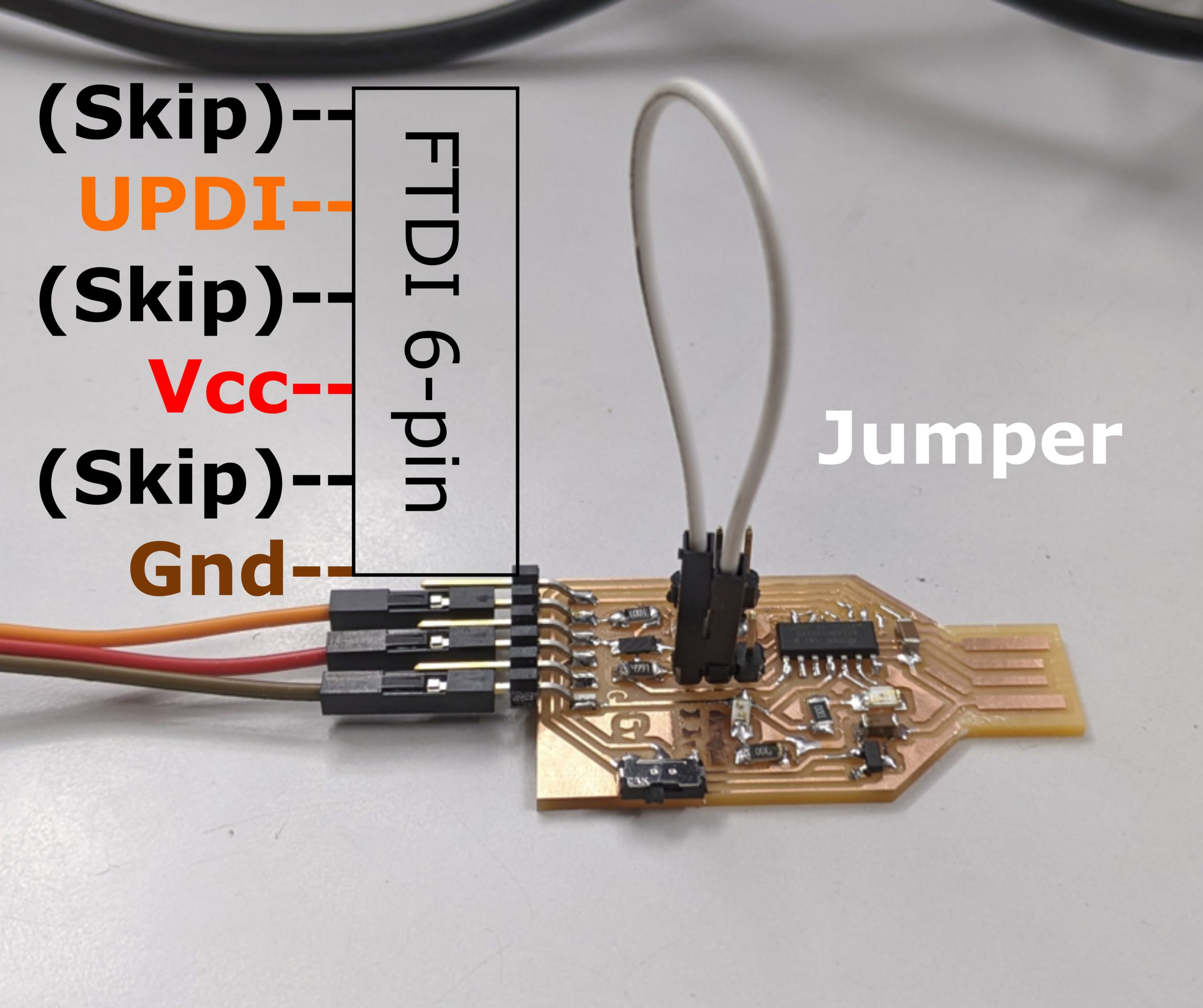
Wire up the samd board as shown below. The white wire is the jumper described above to put the board into UPDI mode. The other wires connect to a target board.
To program other samd chips with this board:
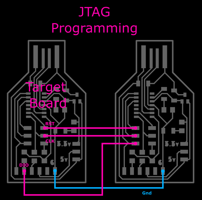
If you want to use this to program other SAMD boards, you’ll need to download this Free-DAP firmware and flash it to this board using the edbg program as explained above. This now becomes a programmer for other boards (called target boards). Connect up the target board to this one correctly (follow pink pin names as shown in the explanation below) and then you can program the target SAMD board with some firmware using edbg as well.
Note that the pinout for the programmer for a target samd board.
FUTURE WORK:
I’d like to take a page from Adafruit’s book and make the Free-Dap project into an Arduino project. Though I I’m pretty sure you can’t flash a bootloader to a SAMD using avrdude (hence the use of edbg). Adafruit’s solution is to have you load the bootloader to an SD card connected to the target board, then the arduino project just dumps the data from the card into the target board’s FLASH. Instead, I think I’d rather take a note from how pyupdi.exe was added to the Arduino IDE and simply include edbg.exe with it instead.
I’d like to make this same board also program ISP chips like the attiny45 or bare Atmega328s, but it isn’t a priority. It should be possible to do this through the ArduinoISP file but…. meh.
For our daughter’s birthday, we noticed how much she seems to enjoy dollhouses so we decided to build one for her. She has plenty of dolls she could use with one, by she doesn’t have the house itself. We have always made her gifts (Last year was a ukulele — yea, yea, we know she’s way too young for it yet… give it time) and we really didn’t want to buy a dollhouse made out of a whole barrel’s worth of oil. Since I’m no CAD star, we looked online for good plans to use.
We came across this Etsy seller and in particular this design. For less than $15 we got the plans which can be used for either a router or a laser cutter and either 5mm or 6mm plywood. For $20-30 we got the flattest and prettiest sheet of quarter-inch plywood from home depot and had it cut in 2′ x 4’ sections to fit in my car and my machine.
At the bottom of this article I have a bullet checklist with a quick reference of all my tips for this project.
My machine is the Xcarve which has the cutting area of about 32”x 31” and the dollhouse plans are HUGE in comparison, so I have to make separate panels for each piece and can’t cut all in one go. I found that the Xcarve is nowhere as good as a shopbot in terms of precision and rigidity so I ended up doing a lot of small test cuts rather than large cuts anyway.
The first hurdle I had was that while the plans I bought came with 4 different file formats, (Abode Illustrator, AutoCAD dxf, CorelDraw, and SVG) When I imported the SVG into Easel, it garbled some parts. Some parts were solid shapes and I could not simply select to cut the outline of the shape. The problem was that Easel likes to have “closed” so the lines used for decoration (like the shingles) wouldn’t cut.
I’ve only cut a couple of projects with Easel which I find much simpler to use than other CAM/Gcode-sending software, but haven’t had tons of luck with external CAM. This led me to hunt for a better option. I had seen online that MakerCAM could do open vectors, but I found it tedious.
I ended up using Carbide Create (originally for the Shapeoko 3) which is adequate for the most part.
The workflow is as follows:
Open SVG in Carbide Create –> build toolpaths –> export Gcode file –> import gcode into Easel –>Send to machine.
If you use another machine or controller software, just replace the last 2 steps with your software.
I found the default feeds and speeds in Easel were way too conservative. For each toolpath, I tested on the smallest part of the dollhouse, the windows; which I needed a bunch of anyway. Playing with the SVG showed that the dollhouse design had dogbones in the interior corners (as it should) and those were approximately 1/8” in diameter which gave me the size endmill I needed to use.
The order you cut the line in the design actually matters. You want to cut all decorative engraving first, then interior cuts, and finally the outlines. Select all the design elements you want engraved (if your design has any) and create a toolpath for them. In my case all the open shapes in my SVG file (which Carbide Crete shows as pink) are what I want to engrave. Holding Ctrl, I click each line I want, then click the “Contour” button near the top left of the screen. This opens the “toolpaths” section which you can always get back to by clicking the green “toolpaths” button at the top of the screen. I select a 1/8” (0.125”) flat endmill for my tool. In my case, I created my own tool to play around with it. Then to override the incredibly conservative default feed rates, uncheck “Set speeds and feed automatically” so you can type in the boxes below.
Since I’m using a 0.125” endmill, the typical stepover and stepdown rule of thumb is these should be no more than 0.5*endmill widthwhich in my case is 0.056” each for the maximum speed. I am using a 4-flute 1/8” bit at 10,000RPM, so I should be able to fly through these cuts. The default feedrate is 12.5 inches per minute (IPM). Easel’s default for a single-flute 1/8” is 40IPM. Since my bit as 4 times as many cutting edges, it’s able to remove material about 4 times as fast as a single flute but I set the feed rate to 40IPM. The 10,000RPM is too fast for what I’m trying to do, but that’s as slow as my router will go.
The next step is to set up the type of cut, max depth, and if you want to add tabs. Since these are superficial cuts, I want to just have the center of my endmill follow the path of the line so I use “no offset”. Since I’m starting my bit at the top of the material, I leave “Startdepth” to 0.000in. I only want an engraving so I use 0.06 inches depth. My material’s thickness is 0.21in so this should be a nice relief. It is also deep enough to not have issues with my unlevel machine. As long as I get the impression of the lines it is OK if they aren’t all the exact same depth, though this is something I should fix in the future. There is no need for tabs on this cutting path so I ignored that option for now.
At this point you can try to see the simulation of the cut, but as of the version I am using the simulation is not very accurate as shown in the full simulation of the part below. Several lines are completely missing (which actually did cut just fine) and the engraved contours have random jagged areas (which don’t appear in the real cut). I recommend avoiding the simulation in this software at this time.
I saved the engraved cuts as “siding” which you can see highlighted in red below.
The next set of cuts are all the interior cuts such as the doorway and the slots. Holding Ctrl, click each item you want, then set up a cut for the interior (the default selection). Don’t forget to change the stepover and feedrate, otherwise it’ll take you many times longer to finish the cut. For the larger areas (not the slots) I added tabs. Tabs on these pieces are areas that don’t cut completely through so the interior part doesn’t wobble around and break stuff when it is cut out. To add tabs, in the toolpath simply click “Edit tabs” and then click on your shape where you want tabs. Tabs appear on your drawing as a little box with an ‘X’ in it. I recommend only having a few tabs (the fewer you have to clean up later) and placing them strategically. For instance, due to the unlevel-ness of my machine, sometimes my tabs are only as thick as the bottom facing of the plywood which is sometimes not strong enough to function as expected. This also depended on the grain direction and direction of the cut. For instance, the tab on the left side of the doorway broke because the grain of the facing ply was vertical and so was the direction of the cut. I also tweaked the tab size to make it hold better and easier to cut when the cut finishes.
I saved this as “InnerCuts” which is shown in red below:
Finally I made the toolpaths for the exterior cuts. I used all the same depth and stepover settings as with the inner cuts. I added some tabs and this toolpath as “outside cuts.” I honestly changed up the cutting speed to up to about 55in/minute and didn’t really see any detrimental results. You can play with these settings to see what works best for your job and set up.
Once all the toolpaths are set up they need to be exported as g-code. While you can export them all as one file, and they would execute top to bottom, I strongly discourage this. Export each one separately because if something happens and you need to recut (maybe you didn’t go deep enough on the first try, etc.) you can always go back to 0,0,0 on your machine and make tweaks to the starting position as needed and try again.
I imported the gcode files into Easel.com to send to my xcarve. You can import gcode by going to File—> Import gcode.
I loaded the three files in the same order as I had created them. Engrave, then interior cuts, then exterior cuts. Each one is automatically loaded into its own “workpiece” as shown at the bottom of the screen. In this example, I actually only did the bottom wall because I forgot to save screenshots from the workflow above. Just note that whatever you set up in your toolpath should be shown in Easel.
Midway through the project, Inventables added the easily-accessible Jog feature to Easel which I found to be incredibly helpful. Since then, there are lots of new features that have been added.
I loaded the wood onto my machine. I was using 2’ft x 4ft sheets of 1/4″in Sande ply. We actually bought two 4ft. by 8ft sheets at the orange big box hardware shop and had them cut it to the smaller size for us to fit in the car.
The xcarve can’t cut the full 4ft length, but I loaded it into the machine without shortening it. This is because once I cut a full-size panel, I then flipped the plywood around and cut another piece on the previously unreachable area.
To mount the plywood, I use the same method I used for manually planning guitar blanks in the past with great success.After laying down the plywood on the machine with the bowed par facing the table (bowed edges flexing upward)and getting it relatively straight and in line with the X and Y motion of the router I laid down a strip of 2” masking tape on my spoilboard halfway under the wood running the length of the board. A tip here is don’t align to your rails or you’ll have a bad time.
After realigning the plywood, I go back and glue the edge of the board to the tape using a high-temp hot glue. To flatten out and bowing the in wood I use my free hand to apply pressure an hold until the glue is hardened, or you can set some clean heady books on it. You don’t really want the glue under the wood, just along the edges. Since we laid the bowed part of the wood into the table, that’ll make it easier to not have a ”bubble” in the middle of our wood that would mess up any cut depth there.
Throw your 1/8” downcut endmillinto the collet and you’re about ready to cut. You want to use a downcut endmill because it if there is any bow or warping to the wood, as it cuts the force of the flutes will put downward to help flatten the wood. This also leaves a much nicer finish on the top of the wood. Sadly, I didn’t find all this out until after I made all my cuts and as you can see below, had to manually use a razor blade on all edges to clean them up.
Once the glue is set, I turn on the machine and click “Carve” in Easel. I can then jog the router to the bottom left corner just to the interior of the wood by about the size of my bit on each axis. This will give me a margin of error incase I didn’t align my tape very well.
After zeroing X, Y, and Z, I jog the z down slowly until the bit presses about 0.1” into the wood. This will help me realign if I need to hit the E-stop and lose my home coordinates.
I quickly turn the router on and off to make a small indention here. If something catastrophic happens and I hit the E-stop or lose power and my machine forgets its location, I can manually adjust my X and Y locations until the bit fits snuggly into this divot and I know I’m pretty close to my original zeros. I zero the X and Y axes at this spot. Lift the bit and move over the wood just next to this divot (I usually move X to the right 1”) and bring the Z axis to touch the top of the wood. I actually put a little pressure on the wood by a couple 0.001” movements.
Part of the workflow in Easel allows you to zero the Z axis by itself after you confirm your location and material thickness. I zero the Z axis at this point. Then in the Job menu, I bring the bit up a touch and move back to X=0 (move X back to the left 1”). Then you are ready to cut.
It’s loud, so wear ear protection. Also wear a dustmask with the appropriate particulate filters. I have a dust boot on my machine, so I set that up. The vacuums I have for my dust boot consist of a household vacuum we’ve had for like 15years that recently lost a wheel and a tiny shop vac. Neither of these were designed to run for hours on end in 90+ degree weather (in the garage with the door open in the middle of NC summer). They both overheat during the cuts so I cycle them out as often as I can. I also run my air filter the whole time and for a few house after I am finished. You might think that with the door of the garage opened you wouldn’t need this but you’d be wrong.
While cutting, if something isn’t right, it is always best to hit the Stop button unless there’s a serious emergency (like someone getting hurt). If you hit the normal stop button (wither in Easel or on the Xcontroller) the Xcarve will finish its current cut, raise the bit to the safe height and bring it back to X0,Y0, Z(safe Height). This way, you can make simple modifications to either the code and try again without losing your position. If you hit the E-stop button, the machine completely cuts off and disconnects from the computer. This will lose your current position. You’ll have to try tot manually set up your X, Y, Z which is never quite correct. That’s why we made that divot in the beginning though. Just in case you hit E-stop you can jog the bit back into that divot, raise the bit, move over and set the Z height again just as before and you’ll be kinda close.
Once all 3 cuts are finished, your part is still stuck in the workpiece because of the tabs. The easiest way to remove the tabs is to use a chisel. Place the flat side of the chisel against the part you’d like to keep and give it a stern whack with a mallet or hammer. This should break the tab and leave you with a relatively clean edge.
To remove your stock material from the table, simply pull upward near the end of one edge and the hot glue should peel off the tape. You can reuse this tape a few times before having to reposition it.
Once I had cut all the dollhouse parts, I cleaned up the edges with a box cutter and razor blades and sanded everything with 220 grit sand paper on my orbital sander to flatten it a bit. The 1/4” ply is slightly thicker than the metric 5mm of the design do for the tabs to fie correctly into the slots, I had to make sure to sand these a bit more. It’s ok if they fit a little loose too because when you add shellac it thickens the piece, then you can put on the twist-knobs to tighten the tabs to the faces of the part with the slot. This really is a genius design and works well if you sand it enough.
After the initial fit, I went back and had to sharpen the interior angles of all the tabs so they’d fit flush with the slots. Without this the design would never work.
I used my box cutter and some tiny files for this. You don’t want any overhangs because when you seal it in the next step, anything that is a soft burr of wood becomes a tiny razor blade or needle when the sealant dries on it.
Take everything outside and shellac it because Sande Ply smells horrible! I think it is formaldehyde in the glue. I sat all the pieces out in the sun for a couple of days (each side getting 1 full day of sun) in the 90+ degree heat which drove off the majority of the stank. I needed to seal it though to prevent exposing my kid to VOCs. Shellac is a natural ingredient made from bug poop dissolved in ethyl alcohol. It is FDA approved (used to coat pills for decades) and often used for baby cribs. Seemed like a great option. I had bought a half-pint of shellac and did it by hand which took forever and didn’t look great. I recommend you buy spray cans of it for fast even coats. Three or more light coats work best for sealing. Make sure to sand with 200 grit paper between each sanding and let it dry for a couple hours between coats. The result slightly darkens the wood, smooths the surface finish, and most importantly, completely seals all the pores of the wood so no chemicals will get in or out of it.
We had to sand the tabs a bit more before it fit back together, and not all the toggles cinched without breaking the tabs. No big deal, that’s why Ii have glue.
This project took quite a while to complete, mainly because of the finishing steps. It took a full 3 days of figuring out my workflow and cutting on the machine (I messed up a few times too in the learning process of course), another couple of weeks for clean up and sealing as I only worked on it on the weekends.
The final result: My daughter absolutely love it! She immediately began playing with it as soon as I brought it in the house. It isn’t the most ornate, or even well-built but I’m proud of it.
Ok, so here’s the cheatsheet for this project:
Get plans for the design. Either make it yourself (which could easily be several posts in itself) or buy them.
Carbide Create is a great offline tool for generating toolpaths.
Make sure to change the step over and depthEVERY TIME you create a toolpath unless you are immortal and time is meaningless to you.
Make sure to check the the start depth and ending depth before exporting the gcode
Change tabs to make sense. I did 0.3” thick and 0.118 tall since my stock material bowed a bit and I was using a 1/4” chisel.
Export each cut separately
Import gcode into Easel in this order: Engrave –> inside –> outside cuts.
Lay down wood on work area with the bowed part down (edged bending upward) and align 2” masking tape just under the edges
Use high temp hot glue to secure edges of wood to tape using weight to keep it flat if needed
Use a downcut endmill for best results and to help prevent the wood pulling upward in the flutes.
Move router to bottom left corner where bit is just fully inside the edges of the wood and jog Z down a bit. Turn on the router and adjust Z until you create a divot in the wood. This will serve as your way to recapture the 0,0 of the job if E-stop or power failure.
Zero X and Y axes to this point.
Move Z up and move X—>1” and use Easel’s Carve workflow to set the height of the material (which Zeros the Z axis)
Move the X back over the divot
Carve the piece.
Rinse and repeat with each cut
When finished, use a chisel with the flat side on the part you want to keep to remove tabs.
Sand with an orbital sander with 200 grit to remove all the burrs and sharp edges.
May need to use razor blades or hand-sand to get some tight spots
Go ahead and make interior cuts of the tabs square for a better fitment
Sand tabs more than you think you should. They would fit loosely in the slots and the toggles should turn easily when you put the house together.
Let wood sit in hot sun for a day on each side with ventilation underneath (I have a slatted patio table) to remove the formaldehyde stank.
Spray with shellac (don’t brush it on unless you have to for tiny detailed spots), let dry a couple hours, sand with 200 grit.
This is a starting point that I do on every one of my raspberry pi projects. You can branch off from this point to any number of projects. I used to like a screen and keyboard/mouse interface, but this is how to set up a headless rpi that you only control over the network. it is much easier than it sounds.
Hardware:
Raaspberrypi startup kit with power cable and SD card.
Computer (I have windows 10 but there are guides out there for mac and linux as well)
Wireless network to connect to
Maybe a camera to format the SD card?
Software Tools required :
SD card formatter (I use a DLSR camera because sometimes even this tool won’t format the cards right)
Balena etcher to burn the raspberryPiOS to the SD card
Firstly, I downloaded and installed the latest raspberrypiOS Lite to an SD card. Once it was installed, I reinserted the SD card into my laptop and created a wpa_supplicant.conf file in the partition I was able to open in windows (one will be openable, the other won’t be). This file sets up your Wifi settings so you can control the pi remotely instead of trying to find the right HDMI or component cable an display and connecting a keyboard and mouse to it. I can simply ssh into the Rpi and run the scripts I need. This may sound intimidating, but it isn’t too hard at all.
Open a text editor (NOT word or notepad, download something like Sublime3 or notepad++) and create a new file names wpa_supplicant.conf. Paste the following and make sure to enter your WIFI’s credentials and keep the quotation marks.
country=US
update_config=1
ctrl_interface=/var/run/wpa_supplicant

network={
scan_ssid=1
ssid="Put your networks SSID here"
psk="Put your networks password here"
}
That will get the pi on the network, next we need to be able to actually control the Rpi from another computer on the network. To do so, just create a blank file with no file extension named “ssh” in the same SD card partition as wpa_supplicant.conf. That’s it. This empty file just tells the Rpi to turn on ssh, which allows you to connect and control it remotely.
Now you can insert SD card into Rpi and plug in power to boot up.
With my older Rpi3 I give it like 5 minutes depending on the OS. Then you can check to see if your Rpi is on the network. Open the command window in windows (windows key, then type “cmd” then enter) and type
ping raspberrypi.local
You should see a response. If it times out, then give it a little more time to install the OS and try again. If you can’t ping it (communicate with it ) after 15 minutes after you booted t up (or 30min or longer sometimes for a pi Zero w) need to start from scratch because something went wrong in your wpa_supplicant file. Triple check that the file is not saved as “wpa-supplicant.conf” or “wpa_supplicant.conf.txt” For that last one you may need to “show file extensions” in window’s explorer.
I always used putty to ssh into linux machines from windows, but Windows 10 apparently has ssh built right in, so you can just click the windows icon and type “powershell” to open a command window, then enter
ssh pi@raspberrypi.local
We’ll use powershell instead of the Cmd window to allow us to copy and paste stuff into the window easily.
The first time you do this, it’ll give you a warning that it “can’t verify the [raspberrypi], do you want to continue” just type “yes” and hit enter. Then you will be asked for the password. Note that as you type, you will see no letters appear in the terminal. This is normal for password entry on linux machines. The default username is “pi” and default password is “raspberry”. When you type it and hit enter you should see a green line that says “pi@raspberry” which means you are logged into the pi.
The first order of business is to change the default password. type the following:
passwd
Enter your new password and you’re set. Now you can go off doing whatever random things you want to use the Rpi for.
To copy and paste into the SSH window you may need copy as usual form a webpage then right-click into the powershell window (maybe do this twice if you hadn’t already selected the powershell window) and it’ll automatically paste it for you.
Static IP: Next I like to set up a static IP address for my Pi so I always know where it is. This also helps things like streaming a webcam for Octoprint since the address won’t change. Android phones won’t use the mDNS entry of “raspbeypi.local” so if you want to use your phone to control or view things on the pi you need to set a static ip. Do so by issuing the following command:
sudo nano /etc/dhcpcd.conf #this opens nano command line text editor to the IP address file...
My pi is on wifi so I’ll adjust the wlan0, but you can replace this with “eth0” if your pi is using ethernet.
This way I know all my raspberrypi stuff is found at 192.168.0.100. I can just type that in for ssh, or into a browser if I’m running a server on it (like octoprint, hassio, mjpg streaming video, etc.
Remote Desktop: To make it easier to connect to the pi in the future and to remote into it and control it’s graphical desktop from any other computer (such as your desktop or laptop), you can set up your pi to allow VNC. First, in your ssh terminal, we need to enable VNC.
sudo raspi-config
Then use arrow keys to select “Interface Options”. Select “VNC” and you’ll be prompted to enable VNC the server. Then you can exit Raspi-config. On your desktop/laptop/other computer you need to install a VNC viewer which will allow you to connect. Visit https://www.realvnc.com/en/connect/download/viewer/ and install it. You should then be able to connect via the IP address of the pi, login to it and have full access and control as if you controlling it with your keyboard, mouse and monitor.
Remote shutdown:
Next you need to know how to shutdown and restart your rpi safely. It is a computer after all and I can’t tell if just unplugging power will corrupt the SD card, so a safe method of shutdown is required. I use a couple. There’s a script you can add to allow shutdown by connection one of the GPIO pins to ground. This is essentially what you do on a regular computer’s power button. You tell the computer you’d like it to shutdown so it will trigger the shutdown functions. Secondly, you might want the ability to shut down or restart via ssh.
sudo shutdown -h now
or
sudo poweroff
and a restart is
sudo reboot
I’ve added a plugin and scripts to my octoprint setup to do the GPIO and I can shutdown from the web interface.
Now if at any point you mess up and can no longer communicate with the pi (setting the wrong IP address, etc) simply format the SD card in windows or in a digital camera and try again.
I recommend once you get all your settings correct, you backup your Rpi OS periodically. There’s a script that you can use to copy a bootable filesystem to another (can even be smaller) SD card you plug into a USB card reader on the pi.
A few months ago, Jess accidently stepped on one of the ukuleles neck and broke the neck in two. Here you can see the break. It broke at the splice that was already in the neck. The fretboard came off at that spot as well. We had recently build a ukulele from a kit, so we knew what to do.
The first step was to glue the two pieces of the neck back together. I cleaned up any badly-fitting sprigs of wood and mated the two pieces together dry to find the correct length. If it isn’t the correct length, then the fretboard won’t fit back correctly and the scale will be off.
Once I got the placement correct, I used Titebond II mixed with a little water to thin it out and used a paintbrush to apply a thin layer of glue to both sides of the break. I clamped it with a mini cam clamp and left it for 24 hours to dry.
Once this was done, I attached the fretboard piece. Due to the way it broke, I had to file down a couple places before it would fit correctly. I used the same mix of glue and water as before to attach it. I clamped it with two large 24” bar clamps. I used these because the large foot applied even pressure on the face of the fretboard. Again, I left it to dry for 24 hours.
Finally, there was one loose fret and a couple of places where the fretboard didn’t seat fully, so I used water-thin super glue to wick into those gaps and used the bar clamps again to apply even pressure.
With the exception of the fret I replaced being a bit too low, and the chunk missing from the back of the neck, it is as good as new! There is only a very slight buzz on one string due to the fret I replaced being too low and I’ve since been too lazy to fix it. Otherwise the uke plays as good as it did before the accident. I think the key is patience with this type of project. We learned that with the uke kit we built previously. You absolutely can’t rush things else you will ruin them.
We’re running out of space. With photos, astrophotography files, and music recordings and work and just life stuff; we are running low on hard drive space. Over the years we’ve bought a few external USB hard drives but even those aren’t manages well and being portable get moved around a lot. That’s not the safest way to handle hard drives. Unless they are SSDs, they can be damaged by moving them around and such. We needed a better solution. I prefer using GUIs to set things up but will for through the terminal if I have to… I just haven’t used my unix fileserver skills since I worked in IT and my linux is a bit rusty as well.
Googling around you’ll find a ton about setting up a NAS or RAID5 or somesuch, but that’s overkill. I’m not looking to spend any money with this, otherwise I’d just have bought yet another portable drive. I already have a bunch of hard drives full of stuff (and honestly, there are a LOT of duplicates of each file taking up tons of space from the crappy way I store my backups). I want to use those drives and be able to clean out the duplicates to gain space. The first step is to build a basic file server.
I had a linux machine (my workhorse during grad school) that wasn’t being used, and bunch of old hard drives that I wanted to use/access It was a variety of drives from old PCs (back to win XP actually, and even older). I had a few external drives that broke so I just plopped them into this machine as well. I didn’t want to format them for a RAID or anything as they were all different sizes and I had data like pics and projects and work stuff from ages ago on them I wanted to keep. The best solution for me was the JBOD (just a bunch of drives) style server. All the NAS examples looked annoying to setup and I’d easily forget what I had done to set them up so JBOD it was. I couldn’t find any single document explaining how to do all the steps I wanted so I spent a couple of weeks failing in my spare time… breaking and unbreaking my linux fileserver and documenting the working parts here for when I need to work on it again. I prefer doing things with GUI if possible, but I’ll do some things using the terminal because you just have to but I tried to keep it to a minimum.
Installing Linux:
If you don’t already have linux running on this computer, I suggest you install it. It sounds hard, but it is super easy to do actually. Just download any flavor of ubuntu you like (lubuntu, kubuntu, linux mint, cinnamon, etc.) I recommend the versions that say “LTS” as those are supported for 2 years or so. There’s a lot of options here.
Install linux without formatting hard drive or losing data:
Download Wubi. This will let you install linux without killing your windows files or messing anything up. you can always uninstall linux later if you want using this method.
Start clean on either blank hard drive or format an old drive:
Download ubuntu flavor you prefer
Format a USB flash drive that’s at least 2GB (lubutnu and xubtunu) or 4GB (all other flavors).
Use Balena Etcher to burn this ISO file to the USB drive.
Once finished, you can reboot your computer.
Enter the boot menu when you see your computer’s startup logo (before windows logo) by pressing either F10, F11, F12, or the delete key. Different manufacturers have different keys they choose for this.
Select to boot off the USB drive.
Doubleclick the icon on the desktop to install *buntu. Follow the menus or youtube videos on how to install it.
Remove the USB drive and reboot when done.
I was already running ubuntu so I just needed to put all the drives in the computer case. I could have 2 drives that were IDE on the same ribbon cable, and 4 SATA drives on the motherboard of my old linux box. Sadly, that’s all this mobo could accommodate. I see spots for 4 more SATA drive on the PCB but they aren’t populated. I filled all 6 spots with drives, making sure that all the drives were set up as slaves except the bootable one (see another post about how I set that up). I also had a TON of USB ports on this motherboard as well (literally 6 on the back, 2 on the front and I added 2 more to a breakout cable inside for a total of 10 USB ports). These can add more portable drives and other drives with some of these awesome USB to IDE/SATA drive cables I have to the server. As I loaded these drives in the bays I made a note as to their serial numbers and capacities. I wrote it on paper, but I also used a sharpie and wrote it on the chassis so I could keep track of what is what and where.
When I turned the machine on, I went into the BIOS and set up the boot order for the hard drives so that my /filesystem always boots first in order of hard drives. When booting the linux machine, hold the Delete key to enter BIOS. Then go to Advanced BIOS Features.
Next select “Hard Disk Priority”. Here’s what that looks like:
Finally, use the arrow keys to select a particular hard drive (the one you want to boot from) and then use the + key to increase its priority until it is number 1:
Once this is done, Hit F10 to save and exit BIOS. It will reboot the machine into linux as it usually did.
Accessing all the Hard Drives:
Open your ubuntu menu and search for the “disks” program. This should be part of gnome-system-tools, which is a standard program in ubuntu. If you don’t have it then open your package manager and search for it. Mark it for installation and click the “Apply” button. or open a terminal and enter the following:
sudo apt-get install gnome-system-tools
You can copy that line of text paste it into the terminal using ctrl+shift+v to paste in a terminal.
All your hard drives should be visible in the Disks app. It lays out all the gory details. Serial numbers, model numbers, etc. Click each drive in the left and note what the “mount point” is for them. I have my Filesystem (this is where I installed the linux operating system) and /home mount points on separate drives. /home is like the user folder in Windows with a folders for Desktop folder, Documents folder, etc. Separating this from the operating system installation file tree allows me to reinstall linux without breaking my user’s documents and settings and Desktop items, etc. I have another post on that and it has served me very well over the years.
For my other drives, they have mount points that start with /mnt and end in a weird code. That code is the UUID (hardware ID) for that hard drive and it isn’t very descriptive for humans. Let’s change that to something helpful. For instance I changed my 1TB drive’s mount point to /mnt/_old_1TB_MyBook
Once all the drives have normal names click the link to one of them and it’ll take you to the folder in your file browser. Go up one directory to see all the hard drives. You’ll note the old folders with the UUIDs in there as well as any old names you had mounted in the past, but they are empty. Only the mount points you named in Disks are connected to your hard drives. You can just delete the other empty old mount points. You have to be root to do so. I used the terminal and the command sudo rmdir <folder name> to delete the ones I was CERTAIN were empty old mount points.
All we’ve done here is essentially modify the /etc/fstab file which contains drive mount info. Lots of other tutorials out there can show you how to do this in the terminal if you want to know how.
Now we need to install all the other software we’ll need for the other steps of setting up the server. in your start menu, search for your package manager software. Mine is “Synaptic package manager” and install the following (make sure you check the box next to these entries, select “Mark for Installation” and when all are selected, click the “Apply” button.) Don’t be surprised if some of these are already selected, just ignore them then:
gnome-system-tools
samba
samba-common
python-glade2
system-config-samba
Or you could open a terminal and paste the following which will install them all for you automatically
Once these all install you will create your linux users who can access this machine. You need linux users to be able to create Samba users. Samba is the file server software. From your start menu button, search for the app “Users and Groups.” Add whoever needs users for the fileserver.
Now you can start fiddling with Samba, which is the actual fileserver software. Since there’s no icon to select to load this app, you need to open a terminal (hit ctrl+alt+t) type or paste:
sudo -H system-config-samba
You can copy that line of text paste it into the terminal using ctrl+shift+v to paste in a terminal.
You have to enter your password, but then a window should pop up. The very first time I did this I got the following error:
SystemError: could not open configuration file `/etc/libuser.conf': No such file or directory
ok, so the file doesn’t exist… I’ll simply make a blank file there and try again.
sudo touch /etc/libuser.conf #creates a blank file named libuser.conf in /etc folder
sudo -H system-config-samba
Success! It opened!
Now we need to figure out which folders we want to share and how they are set up in linux.
As we saw before, the internal hard drives all have mount points in the /mnt folder. So let’s create a share for that. Click the big plus sign button and make yours match mine below. Be sure to click the “Access” tab and make it open for everyone.
Do the same kind of thing for the /media folder. This is where any USB storage devices will mount to by default.
And finally, I have a TON of files on my old desktop and user folder, so I want to make the entire /home folder accessible as well. You have to be careful with this though because if you allow all users (and even guests) edit access to your home folder, they can delete stuff, and snoop to their hearts’ content. Any sensitive data should be locked so that users are required to log in and can only access their files. If for example you wanted each linux user we created earlier to access only their home folders, you’d set that up as /home/adam then you could set the access rights to only allow user “adam” to view it.
Once you’ve set this up, now you must create the Samba users. While in the same application, select Preferences –> Samba users. Here you will add a new user with the same name as each linux user. You will select each user from the “Unix user” dropdown box (this is why we had to create all the users before). You can have the same or different passwords than your linux login. Once you added everyone, close this app. The steps we just took replace the manual process of editing a configuration file for Samba. This is a plain text file stores in /etc/samba called smb.conf and this is usually what most tutorials will do, show you how to edit this file manually. I didn’t have luck with that. Also, you might see tutorials using a tool called gadmin-samba however when I used that it completely hosed up my system hardcore. I had to purge all samba stuff, delete all the files and start from scratch several times to fix the issues.
File/Folder Access Rights:
The final step here that is required is to set the access rights of each folder you want to share. This is important because unless we change these permissions, we will end up only being able to VIEW files and folders on the server but we can’t create new files, paste, move, or delete anything yet. To fix this we need to change the permissions on the folders we set up to share.
We need to open the folders as root or administrator. Depending on the file manager software you might have different ways to do this, but in mine you simple right click ANY folder and choose “open as Administrator” or “Open as root” then I can simply navigate to the filepath “/” If yours doesn’t offer this, then open a terminal and type in the name of your file manager but call it from sudo like one of the following lines:
sudo nautilus /
#or
sudo nemo /
#or
sudo caja /
Right click on the folder of interest, for example “/mnt” and view the Properties. Click the Permissions” tab and make sure that they all show the ability to “Create and delete files.”
Or you can give others the ability to look at files in your home user folder, but not create or delete like this:
sudo chmod 755 –R /home/adam
And you can block others from your folders and have them only viewable and editable by you like so:
sudo chmod 700 –R /home/adam
On the Windows machine:
Now your fileserver is set up you need to access it. Go on your windows machine and open a file browser window. Right-click on “This PC” and select “Add a Network Location” Click Next until it asks for the location. Click “Browse” and wait a minute for it to search your network. You should see your fileServer’s name pop up in the list. Click literally any folder under the fileServer and select Next.
Shorten the terribly long name it gives you (I just delete the highlighted part) and you’re done.
It’ll pull in the other accessible folders on that drive as well. Now you should be able to access and edit anything on those folders on the fileserver. To get to this again simply choose the fileserver option in the left-pane of the windows file explorer. If this doesn’t appear, then make sure your server is turned on and is on the same network as your windows machine and repeat the instruction in this section of the post.
The first time you visit something in here it might ask you for a username and password. Just enter one of the Samba username and password combos we created earlier. You can make it save these credentials and never ask you again if you’d like.
Cherry on top – Remote Shutdown of server:
If you don’t want to connect a keyboard, mouse and monitor to the screen just to shutdown the fileserver, you can do so remotely by installing and using SSH. SSH is a way to securely tunnel into the fileserver’s terminal remotely. That way you can send it the standard linux shutdown message from your windows PC when you are done with it for the day.
Open synaptic and you should select the following:
or run the following command:
sudo systemctl status ssh
This will install the needed files for SSH. Next, we need to let the firewall built into linux know you want to allow ssh. In a terminal window run the following:
sudo ufw allow ssh
Now you can go to the windows computer and use putty.
Enter your data here (keep the port as 22) and when you click “open” a black command window will pop up asking you who you want to login as. Type your linux username and hit enter and it’ll ask for a password. Now you’re commanding the terminal of the linux machine from windows. You can do literally anything the terminal can handle. You can’t do anything that requires GUIs though this way. That’s fine though because this is enough to send the reboot or shutdown signal. The shutdown takes about a minute before it actually shuts down, so don’ t think it isn’t doing anything, just give it some time.
sudo shutdown
#or
sudo reboot
Remote Desktop:
If you want a graphical environment for controlling your server, there’s 2 options. One is to simply remote Desktop into it. There are many ways to do this, but the easiest is to simply install and enable the xrdp app on the linux machine and use the built-in RDP app in windows to connect.
Open synaptic package manager and search for xrdp and xorgxrdp. Mark it for installation and click Apply.
Once this is done, go to the in the App search, look for “System Settings”
Go to Sharing and make sure Remote Login is ON.
Next, in system settings, click “Network” in the left column and then click the gear button next to your wired (or wireless) connection. This will give you your IP address. It should look similar to your router’s address. Mine’s 192.168.x.x. You’ll need this to connect in windows.
To do all this in the terminal on the linux machine (or through SSH) run the following:
This last command, ifconfig, will give you a screen showing you the local IP address of the machine. It should match closely to your router’s address. Mine is 192.168.x.x so I look for something that matches that. You’ll use this on the windows machine.
Now on the windows machine, click the start button and type “RDP” and hit enter. Type in the IP address of the linux machine.
I found an easier way. Simply right click on the fileserver in your explorer folder and select “Remote into this machine”
When you click connect, you’ll be able to login. I had a little trouble with this connecting. I tried all the selections in the dropdown menu a couple of times and on the 2nd or 3rd try it worked. Once I was logged in I got an error asking me to login to create a color device over and over. After entering my password 3 times I just canceled it and the window stopped popping up. I haven’t done this in like 15 years, but I don’t remember the experience being so crappy. I can access the desktop, but it is displaying a GNOME environment instead of the Mate environment I have installed on the linux machine. Nonetheless I can get do things graphically without issue.
Other Thoughts:
The way I’ve done it is quite insecure. I’m allowing Guests on the network access to create and destroy all the shared files which is kind of dumb… I’ll live with it though because I will only turn this fileserver on if I am immediately accessing the files on it, then immediately turning it off again. In that short time I hope I don’t get hacked…
Storing all your files in one location is not the best for preservation. You can make a personal cloud like Google Drive, Dropbox, Box, OneDrive, Apple Cloud, etc. by using the Unison program. It essentially synchronized two folders. These can be on the same computer, one on a portable USB drive, or even across the network. Anything added, modified, or deleted in one folder is automatically synched to the other in both directions.
Previously, I had some luck with using my file-brower’s “share” plugin. Nautilus, Nemo, and Caja all have their respective “share” app you can install in apt-get or synaptic eg “caja-share“. This will allow you to simply right-click on a folder and select “share settings” where you can set this up yourself. The problem with this is that this info is NOT stored in the basic /etc/samba/smb.conf configuration file. In fact, it is nowhere to be found anywhere in that folder. This is because this plugin stores this info in the following path:
/var/lib/samba/usershares
To create the Samba users and set up their SAMBA passwords (these can and maybe *should* be different than their linux user passwords)
sudo smbpasswd –a user1
sudo smbpasswd –a user2
Now enable the users
sudo smbpasswd –e user1
sudo smbpasswd –e user2
Check the status of the samba server. You should see “active” somewhere. If not, you hosed it somehow. Tips on how to fix this at the end…
sudo systemctl status smbd
Restarting samba (after every big change to users, folders, etc you should do this. Or you can reboot the machine, which is foolproof method of restarting the server the right way)


 A few months ago, Jess accidently stepped on one of the ukuleles neck and broke the neck in two. Here you can see the break. It broke at the splice that was already in the neck. The fretboard came off at that spot as well. We had recently build a ukulele from a kit, so we knew what to do.


