
 I’ve had a FTDI cable for a while for testing serial communications between my microprocessors and my computer and for that job, it works great. However, I recently grabbed a couple Ardweenies from Solarbotics and decided to use my FTDI cable to program them. The FTDI cable doesn’t have an automatic reset, so you have to push the reset button on the board at exactly the right time when trying to program it from your computer. This causes tons of frustration.
Oddly, a few days of experimenting with the arduinos, my cable got a short in it. While fixing the short, I was surprised to find out that the FTDI cable uses the same chip as the Sparkfun Programmer (which has automatic reset) so I went about modifying my cable to include this feature.
Modifying the cable is much easier said than done, but since I got it working, I figured I’d do a write-up on it in case anyone else wants to give it a shot.
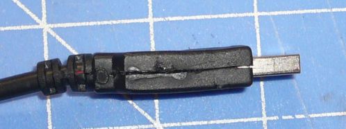
The first thing you must do is remove the molded plastic housing around the USB connector. This is made by placing the PCB into a mold and pouring in liquid plastic, so it is literally molded to the circuit board. I opened mine very carefully with an exacto knife by slicing along the seams. Once the seams were slices, I peeled the plastic back to reveal the PCB.

At this point, I found the problem with my cable, the ground wire had broken off the board. I quickly fixed that problem and began trying to find out how to modify the circuit.
The problem with this cable is that the end connector has all the correct outputs for arduino programming except one. The Green wire on the connector connects to the RTS pin of the FTDI chip instead of the DTR pin. The DTR pin is used to automatically reset the arduino board before programing. I looked up the chip and found it to be the same one as on the Sparkfun Programmer. This was great news. It meant that I could modify it to auto-reset my arduino so I don’t have to push the reset button every time I try to download a sketch. So I looked up which pin on the FTDI chip the DTR pin was.
In the datasheet for the FTDI chip, It shows that the DTR and RTS pins are side by side (pins 31 and 32.)

Here you can see the view of the bottom of the chip (mirrored form the top perspective)
Finding this on the actual chip was complicated. I had to pull out the Macro lens for the camera just to see the pins.
Testing with the multimeter proved that the DTR pin isn’t connected to any vias or solder pads on the board. The connection would have to be made directly to the pin.This was no easy task. The thinnest wire I had available is from an old wire wrap kit. Even this was too large to connect to the pin. I tinned the tip of the wire carefully, and attempted to use my home made hot air reflow pen, which didn’t work at all. Then I tried a heat gun, which neatly melted all the parts on the board. Finally, I had to manually solder a wire to the pin. The thinnest soldering iron tip I have is about 5 times the size of the pin.
After a couple of hours of trying, and even a couple of good solder connections that broke because they were so thin, I decided to put the wirewrap wire through one of the vias on the board for support. This helped, and after about another hour of attempting, I finally got a good connection. As soon as I verified it, I coated the whole thing in a couple layers of super glue to hold it fast.


The final solder connection covered in super glue.
After the glue dried, I then desoldered the green wire from the board and connected it to other end of the wirewrap wire. To get things to fit back into the plastic housing, I had to mill out the inside a bit with my dremel. Then put the housing back together and super glued the seams. To hold this tight, I wrapped it with a few zip ties until dry.

Now my FTDI cable is better than ever! All I have to do to program my Ardweeny now is click the download button in the program.
Add Automatic Reset to Your FTDI-232R Cable:
I’ve had a FTDI cable for a while for testing serial communications between my microprocessors and my computer and for that job, it works great. However, I recently grabbed a couple Ardweenies from Solarbotics and decided to use my FTDI cable to program them. The FTDI cable doesn’t have an automatic reset, so you have to push the reset button on the board at exactly the right time when trying to program it from your computer. This causes tons of frustration.
Oddly, a few days of experimenting with the arduinos, my cable got a short in it. While fixing the short, I was surprised to find out that the FTDI cable uses the same chip as the Sparkfun Programmer (which has automatic reset) so I went about modifying my cable to include this feature.
Modifying the cable is much easier said than done, but since I got it working, I figured I’d do a write-up on it in case anyone else wants to give it a shot.
The first thing you must do is remove the molded plastic housing around the USB connector. This is made by placing the PCB into a mold and pouring in liquid plastic, so it is literally molded to the circuit board. I opened mine very carefully with an exacto knife by slicing along the seams. Once the seams were slices, I peeled the plastic back to reveal the PCB.
<191>
At this point, I found the problem with my cable, the ground wire had broken off the board. I quickly fixed that problem and began trying to find out how to modify the circuit.
The problem with this cable is that the end connector has all the correct outputs for arduino programming except one. The Green wire on the connector connects to the RTS pin of the FTDI chip instead of the DTR pin. The DTR pin is used to automatically reset the arduino board before programing. I looked up the chip and found it to be the same one as on the Sparkfun Programmer. This was great news. It meant that I could modify it to auto-reset my arduino so I don’t have to push the reset button every time I try to download a sketch. So I looked up which pin on the FTDI chip the DTR pin was.
In the datasheet for the FTDI chip, It shows that the DTR and RTS pins are side by side (pins 31 and 32.)
<FTDIRQ>
Here you can see the view of the bottom of the chip (mirrored form the top perspective)
Finding this on the actual chip was complicated. I had to pull out the Macro lens for the camera just to see the pins.
<685>
Testing with the multimeter proved that the DTR pin isn’t connected to any vias or solder pads on the board. The connection would have to be made directly to the pin.This was no easy task. The thinnest wire I had available is from an old wire wrap kit. Even this was too large to connect to the pin. I tinned the tip of the wire carefully, and attempted to use my home made hot air reflow pen, which didn’t work at all. Then I tried a heat gun, which neatly melted all the parts on the board. Finally, I had to manually solder a wire to the pin. The thinnest soldering iron tip I have is about 5 times the size of the pin.
After a couple of hours of trying, and even a couple of good solder connections that broke because they were so thin, I decided to put the wirewrap wire through one of the vias on the board for support. This helped, and after about another hour of attempting, I finally got a good connection. As soon as I verified it, I coated the whole thing in a couple layers of super glue to hold it fast.
<693> Tantalizingly close to being done, this solder connection broke.
<694> The final solder connection covered in super glue.
<698>
After the glue dried, I then desoldered the green wire from the board and connected it to other end of the wirewrap wire. To get things to fit back into the plastic housing, I had to mill out the inside a bit with my dremel. Then put the housing back together and super glued the seams. To hold this tight, I wrapped it with a few zip ties until dry.
<211>
Now my FTDI cable is better than ever! All I have to do to program my Ardweeny now is click the download button in the program.
If you open the Advanced settings of the USB cable driver in Device Manager, you can just check a box to set RTS on close. That works great with the Arduino software, no hardware mod required. Not sure if this is easily accessed on a Mac.
I run Linux Mint. I’m not exactly sure how to adjust that setting yet. I figured that since I had to open the cable anyway to fix the broken Ground, I’d change pins. After the first few failed tries, I became determined to get it working that way. Maybe it was pride…
Modifying cable is such a great work you really did it very well. Nice job for you and you impress me a lot. Thanks for posting this I will use it as a reference material this is very useful to me. Thanks for sharing.