I finally got a chance to play with the SAMD11C chips FabAcademy has been recommending for a while. I also wanted to learn to use KiCAD a bit more so I made a multi-use board with the SAMD11C which can be used for UART, UPDI programmer, and as a FreeDAP board. You can find all of my files for this project, including the firmware at my FabAcademy gitlab page.
I will be making a modification of the board Quentin designed.
I designed the board in KiCAD by modifying another of Quentin’s boards, the SAMD11C dev kit with USB-A connector.
To fabricate a PCB, I’ll use the Roland SRM-20 mill as well as my shapeoko/X-carve using Fab Mods.
The steps in this project are:
- Download my board files, code, and hex from here.
- Mill the PCB with Roland or other CNC
- Populate (stuff) the board with components
- Flash firmware to the chip
- Use this new board as a programmer or USB/UART
Milling a board on the SRM-20 through Fab Mods:
I’ve posted a more detailed explanation of exporting from KiCAD to a milling machine in this previous post. Be sure to check that out when you get to that part of the process.
Go to http://mods.cba.mit.edu/
Right click anywhere on the screen and select “program” then “open server program” and search for Roland→SRM-20 → PCB png. To use any other CNC (Shapeoko, Xcarve, 3018, etc.) you can select G-code→ mill 2D PCB png. This will accept in a PNG image file and generate the cut file you will send to your machine.

Then we’ll modify this to save a file for us.

If your X, Y, and Z, look like the GIF above, you’ll do an “air cut”. An “air cut” is a test that runs the same code, just offset in the Z axis (and this case X and Y as well) just to make sure everything will cut as you would expect. Then you’ll regenerate your cut file by changing the X, Y and Z defaults to 0s in mods before exporting your cutfile again.
Once the board is cut, it must be populated… Break out the old iron and solder up the design. If you don’t have a switch like the one I used, you can simply install some male headers and use a jumper to select the voltage. The SAMD doesn’t have a lot of external accessories which makes this part a good bit easier than say some of the older FabISP designs.
Once populated, the board needs to have firmware flashed to it. For this step, I will use the Atmel ICE programmer and a windows computer.
First download windows version of edbg which is the debugger tool we’ll use to download the firmware.
I downloaded it to my desktop.
Then download the binary of the firmware. I am using the SAMD11C arduino bootloader core firmware so I can use the chip with the Arduino IDE and libraries. (This bootloader seems to eat up a good bit of memory, even on these ARM devices).
Connect up the atmel ICE programmer to the SAMD board. I used figure 3-8 from the atmel ice manual to figure out the pinout because we are using the Serial-Wire debug (SWD) pinout.
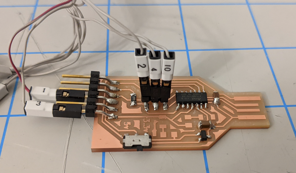
Above you can see the specific pins for programming the firmware with the Atmel ICE. Pin 1 is Target Voltage (Vcc), pin 2 is SWDIO, pin 3 is GND, and pin 4 is SWDCLK. Pin 10 is the Reset.
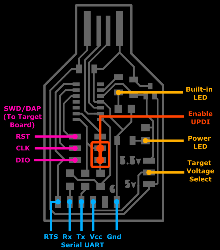
Here are the pins and usage of the board:
Finally you’ll need to open the command prompt in windows, cd to the directory you downloaded these files to and run the following command (assuming you went with the 2nd firmware option above):
edbg-windows-r24.exe -bpv -e -t samd11 -f sam_ba_Generic_D11C14A_SAMD11C14A.bin
You should see:
Debugger: ATMEL Atmel-ICE CMSIS-DAP J42700050854 01.00.0021 (SJ)

Clock frequency: 16.0 MHz

Target: SAM D11C14A (Rev B)

Erasing... done.

Programming.... done.

Verification.... done.
The first time I did it I got this error:
Debugger: ATMEL Atmel-ICE CMSIS-DAP J42700050854 01.00.0021 (SJ)

Clock frequency: 16.0 MHz

Error: invalid response during transfer (count = 0/1, status = 0)
I unplugged everything, replugged it and tried again and it worked.
This firmware only allows arduino to program the chip via USB. Let’s now install the correct board info to arduino so we can do that.
In the arduino software, go to File→Preferences and click the icon next to “Additional Boards” and paste the following:
https://www.mattairtech.com/software/arduino/package_MattairTech_index.json
Then you need to install the SAMD boards. In Arduino go to Tools→Boards→Board manager
Search for “SAMD” and install the “MattairTech” one only.
Once this is installed (it will take a bit of time) We can write some arduino code to run on our new board. Let’s start with a blinky program. Looking at the pinout of the SAMD11C, we can choose a pin to connect an LED to on a breadboard.
(Image source: https://gitlab.fabcloud.org/pub/helloworld/index/-/tree/master/SAMDino.%20Hello%20SAMD11C14 )
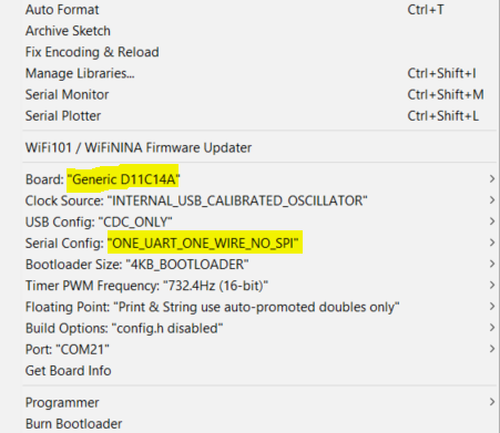
You better make sure that you always use “INTERNAL_USB_CALIBRATED_OSCILLATOR” when you plan to keep this plugged into the USB port for power, or “INTERNAL_OSCILLATOR” when you want tit to be standalone. If you select the other two options, you’ll have to reprogram the firmware with the ICE or a DAP. It basically bricks the chip if you tell it to use an external crystal but don’t add a xtal to your design.
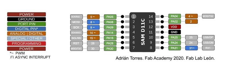
Arduino file to be serial print to test. The pinout is simple. Each output uses the same pin number as the SAMD chip output. This is unlike a normal Arduino.
ATsamD11C14A Arduino pinout

   0 -------------------
  5 | A5                 A4 | 4
  8 | A8 (XIN)        A2 | 2
  9 | A9 (XOUT)   Vdd |
14 | A14             Gnd |
15 | A15             A25 | 25
28 | A28/RST     A24 | 24
30 | A30            A31 | 31
    -------------------
You can download this code to test your board (whether you have a working LED or not). Once this uploads, open the serial terminal and you should see “hello”
void setup() {
   SerialUSB.begin(0);
}

void loop() {
      SerialUSB.println("hello"); //Send stuff from USB to serial port
} //end loop
If you want to test to make sure that your board can now be programmed from the Arduino IDE, you can flash the built-in LED on pin 2 with this code:
int led = 2;

// the setup routine runs once when you press reset:
void setup() {
  // initialize the digital pin as an output.
  pinMode(led, OUTPUT);
}

void loop() {
  digitalWrite(led, HIGH);   // turn the LED on (HIGH is the voltage level)
  delay(1000);               // wait for a second
  digitalWrite(led, LOW);    // turn the LED off by making the voltage LOW
  delay(1000);               // wait for a second
}
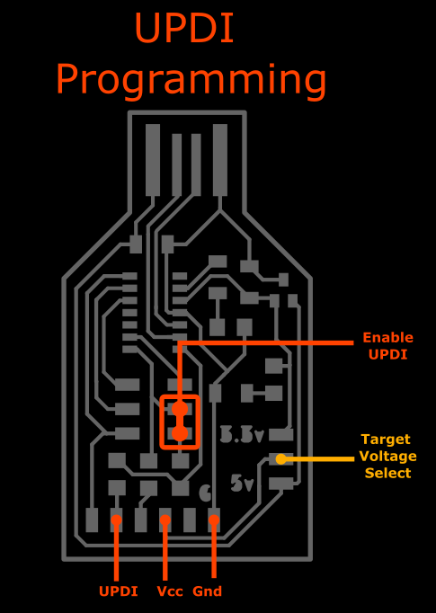
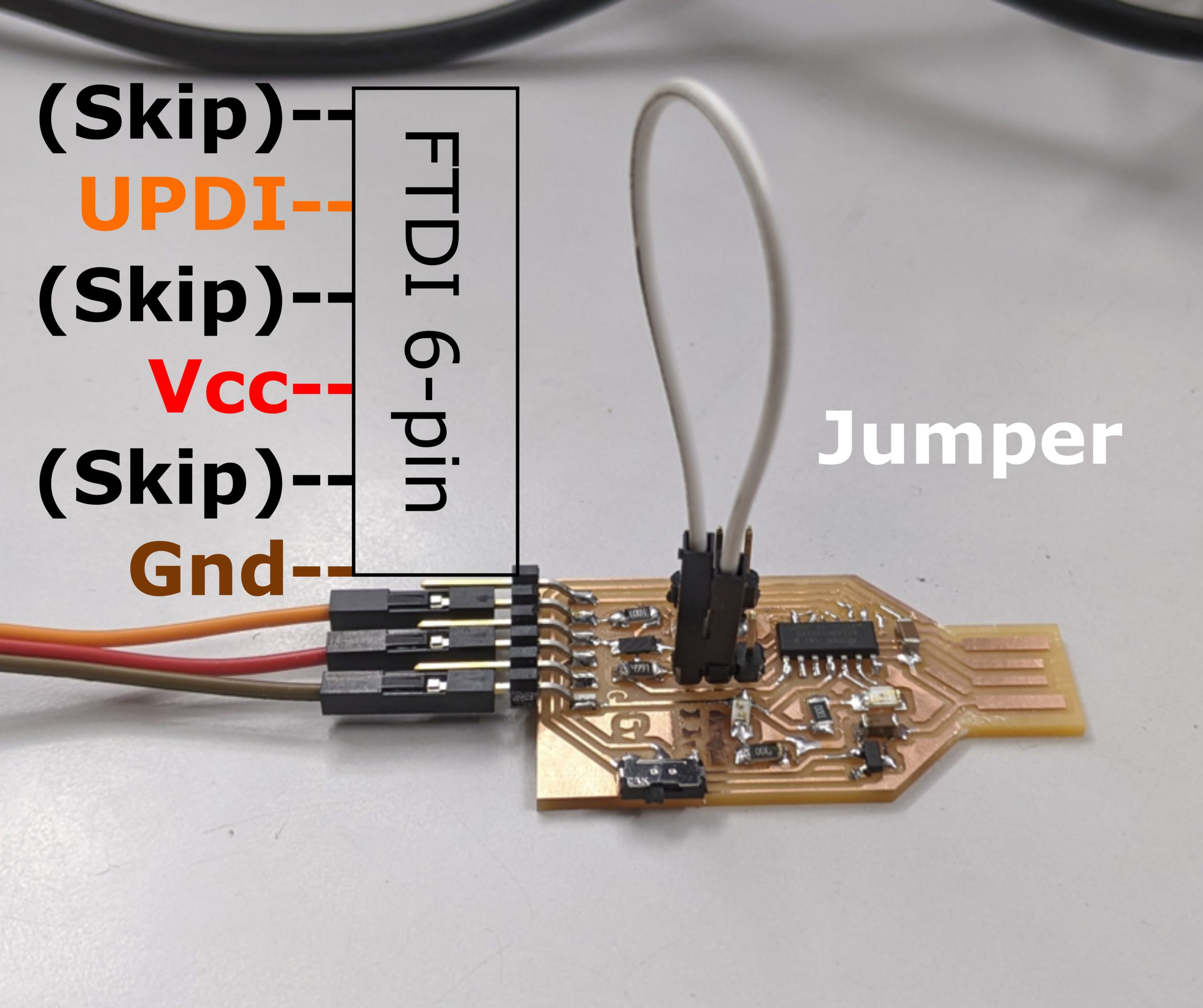
The following Arduino file makes this board into a UPDI programmer when you add a jumper to the appropriate pins (see above). Simply take data from the USB serial port and put it on the output serial port and vice versa.
void setup() {

   SerialUSB.begin(0);
   Serial1.begin(57600, SERIAL_8E2); //Adjust baud rate and use SERIAL_8N1 for regular serial port usage
}

void loop() {
   if (SerialUSB.available()) {
      Serial1.write((char) SerialUSB.read()); //Send stuff from Serial port to USB
   }
   if (Serial1.available()) {
      SerialUSB.write((char) Serial1.read()); //Send stuff from USB to serial port
   }
} //end loop
Program a target board over UPDI:
Once you have downloaded the above serial code to your board, you can use it to program attiny412 or attiny1614 chips over UPDI.
- First, you want to get a Attiny board. Here’s a great simple board to try.
- Get the code from that link to blink the LED on pin 0.
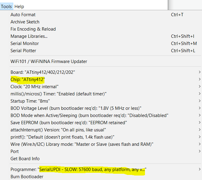
- Most important part==>In arduino, change the chip to the attiny412!!! If you don’t do this, you’ll accidently reprogram the samd which you don’t want to do. If that happens, go back and put the serial UPDI code above back on the samd.
- Change the “programmer” to “SerialUPDI – SLOQ: 57600 baud, any platform…”
- Wire up the samd board as shown below. The white wire is the jumper described above to put the board into UPDI mode. The other wires connect to a target board.
To program other samd chips with this board:
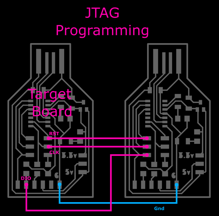
If you want to use this to program other SAMD boards, you’ll need to download this Free-DAP firmware and flash it to this board using the edbg program as explained above. This now becomes a programmer for other boards (called target boards). Connect up the target board to this one correctly (follow pink pin names as shown in the explanation below) and then you can program the target SAMD board with some firmware using edbg as well.
Note that the pinout for the programmer for a target samd board.
FUTURE WORK:
I’d like to take a page from Adafruit’s book and make the Free-Dap project into an Arduino project. Though I I’m pretty sure you can’t flash a bootloader to a SAMD using avrdude (hence the use of edbg). Adafruit’s solution is to have you load the bootloader to an SD card connected to the target board, then the arduino project just dumps the data from the card into the target board’s FLASH. Instead, I think I’d rather take a note from how pyupdi.exe was added to the Arduino IDE and simply include edbg.exe with it instead.
I’d like to make this same board also program ISP chips like the attiny45 or bare Atmega328s, but it isn’t a priority. It should be possible to do this through the ArduinoISP file but…. meh.