Baofeng TP-8Plus, UV-13 Pro, GM-30, and similar radios

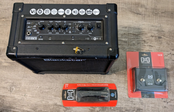
So I was at the bin store the other day and I came across a couple of Baofeng TP-8Plus radios. I’m no expert on HAM radios in general (please correct me on anything I’m wrong about on this page BTW), but I got these two for $7 each so I couldn’t beat it. It turns out, the models I picked up are now a ubiquitous hardware model with different firmware which can be used for multiple purposes.

Firstly, I can’t tell the differences, but the TP-8Plus is apparently also called the UV-13 Pro.. as well as many other models (listed below). There are different levels when talking about radios like this, HAM and GMRS. HAM radio is amateur radio and you have to pass certifications tests for the license. These radios are classified as HAM radios since their broadcast power is too high for GMRS (which is a higher powered two-way walkie-talkie band). To use GMRS band, you need a radio rated for this band and a GMRS license (no certification test required) and your whole family can use the radios apparently. The radios are too powerful as they are for this, however there’s a firmware you can get for them that limits the broadcasting power turning them into GMRS-legal radios (from what I have read..)

Where to get Firmware:

Before doing anything, I took a pic of the current firmware version as shown below. You can see this by holding the flashlight button as you turn on the radio

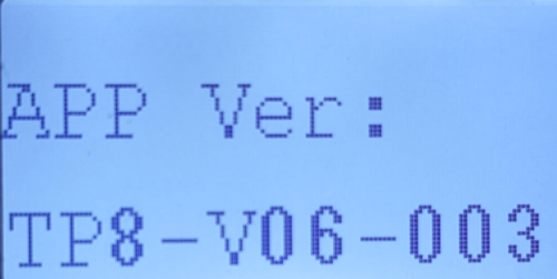
I was unable to figure out how to copy this ROM onto my PC, but I did find an older version of the UV-13 firmware I could use to replace it if I needed to… which I did. I wish I could find the firmware online.

Where do you get firmware? It depends on what you want your radio to do. I have it on the authority of some random dude on reddit and other that this radio’s hardware “is the same for Baofeng UV-13, TP-8, Explorer QRZ-1, TYT TH-UV88, Pofung P15UV,  Rugged GMR2, TIDRADIO TD-H5, Retevis RT85, and Radioddity MU-5, GM-30.”  Firmware for those radios should work here. They each have slightly different abilities, so it is really up to you. what you’d like it to do. Do your research to see what legal licensing steps you can take based on how you want to use your radios. Comment below if you know where to find other firmware for this radio.

For using this as a HAM radio (where you can enter in frequencies manually or scan them in the 2m band) the UV-13 firmware was easiest to find. The only version I came across online from multiple sources was UV13-Firmware-V06.01.013-20211104_01013.bin I was able to successfully install this without issue and I can still write program settings using the P15-UV software.

For GMRS walkie-talkie usage, I came across the Radioddity page with their firmware. It is important to note that after installing this firmware, I had to use Radioddity’s own version of P15-UV branded “GM-30”. The link to their firmware and programming app is here. From what I read, this firmware limits the transmit frequency making it legal to use the radio. NOTE: I am not a lawyer and I have no way to test the radio’s power with this firmware to compare, it is just what I read on the internet.

Programming:

There are 2 programming modes. One for just reading/writing programmed channels and settings, and another mode for updating firmware. There’s a trick to program firmware I describe below.

The software for the Baofeng firmware is P15-UV CPS software. I was able to find a version of it from a company called abbree.  This only works for the Baofeng firmware. I had to get my copy from the wayback machine as the link on their main download page was broken. This is different software than my older UV-5R used. If you have the GM-30 firmware installed, you must use this Radioddity branded version of the programming software.

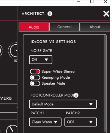
    1. I already had a USB cable for these radios since I had an older model. Once installed you can plug it up to the radio, turn on the radio and connect. In the PUV-15 software, select “Program–>Communication Port” and select the com port. If you don’t know which this is, open windows device manager and look for the COM port that disappears when you unplug the cable.
    2. Next you want to back up and save all the channels and settings from the radio by selecting “Program–>Read from Radio” and click “OK” to read all the default settings. Then you have to click “File–>Save As.” This will save your channels and any program settings to a file on your computer.
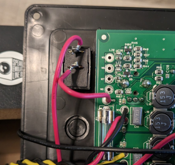
    3. To flash the firmware, download your preferred firmware version (more on this below) and select “Program–>Tool” For this to work you must manually put the radio in programming mode by turning it off, holding down the PTT and Flashlight button as you turn it back on again.  You know you did this right when the screen does NOT come on, but the red light at the top glows dimly.
    4. Click “Upgrade” button on the app to change the firmware. DO NOT INTERRUPT THIS PROCESS or you might brick the device.
    5. Rewrite the channels and program settings by choosing “Program–>Write to Radio”
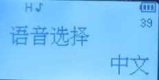
    6. If you were a genius like me and forgot to backup your settings, your menus and voice might now be Chinese.  No problem, simply change the language by scrolling through the menu that says this:

      Then pressing the menu button to edit and the down button to change it to English. Press menu again to confirm the change.

    Licensing:

    Again, I am no expert on the matter, but here’s what I learned from all the forum posts and videos I found on this radio. There is no license required to use these radios as listening-only devices. You can use them as weather radios or even emergency service scanners. If you wish to transmit at all you’ll need either a GMRS license or a HAM radio license depending on what firmware you have and how you plan to use the radio. See the comparison chart below:

    GMRS HAM
    One license covers your family. Licensing process is confusing, so watch a recent tutorial video on the process to find out the steps required. One license covers you. You can allow your family to broadcast, but you must be there with them at the time.
    No exam required Must pass a certification exam (there are different levels)
    To be used as walkie-talkies (eg. in your family) because they are shorter-range transmissions. Connect with community of HAM radio operators all over the country, world, and even on the international space station!
    Use Radioddity GM-30 firmware and their custom programming app. Use Beofeng UV-13 firmware and the P15-UV programming app.
    License last 10 years License lasts 10 years
    Cost $35 Cost $35

Ultimate List of Tips, Tricks, and Tutorials for Fab Lab Students

This post is a not on a lot of techniques for using different types of machines and processes for making stuff. I’ve had this for years but decided to finally publish it. I’ll add to it periodically, but I figured others might find it useful as well. RIGHT-CLICK to open in new windows.

Laser Cutting:

Embedded Systems, Microcontrollers, and Arduino

Circuit Board design and Fabrication:

3D Printing:

Casting and Mould Making:

CNC:

Machines:

Mechanical:

Metal-Bending:

Miscellaneous:


================================================

My favorite Fabrication-related researchers:

Dr. Stephanie Meuller at MIT’s research group

Dr. Patrick Baudisch at Hasso Plattner Institute Human computer interaction reserach group


Teaching Research:

Sketchnoting basics

Graphic Recording

Sketchnote travel journal to get started

Control Theory:

Brian Douglas’s awesome youtube channel explains Control with some great examples.

Kat Kim has another great channel on Controls as well as other Electrical and Computer engineering examples and lectures

George Gillard has a great whitepaper explaining PID controls

Another great PID example is from this Reddit thread

Learning Math concepts:

MathVault – Learn higher-level (college-level) math concepts more intuitively

BetterExplained.com ADEPT model for learning math intuitively

Good sources of materials:

XXXXXXXXXXX    Todo when I’m not so busy or lazy: XXXXXXXXXXXXX

Add sections for PCL shapelock and other named plastics to ultimate FabLab list.

Also add cardboard modeling guy and nibbler tool

Add anodizing alum and titanium, bluing/blacking steel,

And interesting research I like with lasers  hydrographics and uv printers and metal hologram art

How to add a Pedal Control to Your Blackstar ID10 Guitar Amplifier

I recently got a 10 watt Blackstar IDcore guitar amplifier (I had to get a power supply separately). It has a lot of really great built-in effects.  Unlike the larger versions of this amp (the 20watt and 40watt versions) it does not have a footswitch to control these settings. You just have to turn a knob with your hand to change the settings. You can plug this amp into your computer via USB and tweak the controls with the Blackstar Architect app. In the settings for this app, I noticed that there are indeed footswitch options a user has access to, but there’s no footswitch plug on the amp. It is set up for a 2-button footswitch. There are apparently two modes a footswitch can work with the amp.  One mode is called “Default” which allows you to assign each footswitch button to a particular setting (such as “Clean warm” and “Overdrive 1”).  The other option is called “Alternative mode” where you can use one button to increment through the presets, and the other button decrements through the them. I did a bit of googling and found that this hack has been around for a number of years so I got to fiddling…


You can see the parts below. All you have to do is solder up a stereo 1/4″ female jack, drill out the hole in the faceplate, and get a pedal to connect to it. Luckily I ordered 2 of these jacks because the pedal I bought had a janky plastic jack that was broken in the package. You’ll also need a stereo 1/4″ TRS cable like this. The cable must be stereo for this to work correctly. TRS stands for “Tip, Ring, Sleeve”.


Opening the amp you can clearly see the plastic plug on the faceplate (bottom middle circle). This faceplate is reused on the larger versions of the amp. Right next to it are some unpopulated holes on the circuit board.  Sure enough, carefully connecting wires to the right holes here gets the footswitch functions to work! Below you can see the holes labeled (top to bottom) W5, W6, W7, and W8.


I used the biggest drill I had on hand which was 3/8″, then I used an exactly to carefully widen the hole for the jack. Next I soldered up the jack itself. It is important to note that the lower solder plug is actually connected to the tip and the highest one is connected to the ground (sleeve).  Leave the wires 4-5 inches long so they will reach the holes on the circuit board. The way to connect them is as follows:

  • W5 connects to Tip.
  • W6 connects to the middle or Ring
  • W7 is NOT CONNECTED
  • W8 connects to the Sleeve (which is the base part connected to Ground)
  • You can see an additional red wire here that connects to the switch in the image below. You don’t touch that.


Once I had this soldered up , I was excited to use my footswitch. Sadly, when I opened my hosa footswitch, the 1/4 inch jack was loose because the plastic retainer nut was split.   I went ahead and used my other female 1/4″ jack to replace the broken plastic garbage making sure to keep the TRS connections correct.

That’s it! Enjoy your footswitch controlled Blackstar amp!


2nd Weather Balloon (from 2010)

Back in 2010 I was part of a team that sent up a couple of weather balloons on a NC spacegrant. I posted about the first one (which flew straight into a thunderstorm) a long time ago, but with the recent weather balloons in the news, I decided to go back and look up my old photos from the second balloon.  In the pic above the yellow balloon was the first one, the green plot is of this second balloon.

We launched from Monroe Airport in NC and the path of the balloon followed the path of HWY 74, which is the main road in the area. There are a couple of good pics of Wadesboro, NC and Lake Tillery as well.

This one went about 75k ft. in elevation. You can *just* make out the curvature of the earth in some of the photos. We launched on a beautiful clear day and we were able to visually track the balloon’s full ascent AND descent. Fun times! Luckily it didn’t freeze on the ascent so we got some better pics. We stocked this one with a bunch of candy like last time and it was fun eating space candy again!

DIY Soldermask Showdown

banner

Once you fabricate a PCB, it pretty much instantly begins to oxidize. PCBs created in industry are coated with a couple of things to protect them from this oxidation and short circuits. The first is called a soldermask, which is a type of epoxy that literally coats the entire circuit board. If you’ve ever seen a circuit board, you’ve seen the soldermask. It is typically GREEN but can be different colors. For example, official arduinos typically have a Teal BLUE soldermask. Sparkfun uses RED. OSHPark uses Purple.

You can see below just how badly the copper oxidizes after being touched an exposed over time.

unprotected

There are multiple ways to add a soldermask to a PCB. My new favorite method is using Kapton tape (explained at the end of this page), but I have tried and compared a lot of different solutions below.

Epoxy-based:
In industry, they use a specially designed paint or epoxy that is cured with ultraviolet light. This allows them to cover all the traces (the wires) but leave the pads visible so you can solder components on the board. Some folks have tutorials out there showing how to do this, but it is messy and uses nasty chemicals.

Dry-Film Soldermask:
You can also buy sheets of “dry film soldermask” which has the epoxy deposited as a flexible sheet that you adhere to the PCB, then use a photolithography method to harden it with UV light.  This allows you to remove the softer material on the pads you will solder the components to. This material is not readily available, but you can find it from electronics suppliers online. Here’s an excellent tutorial on how to do this process at home.

Tinning Traces:
Another option to protect the traces from oxidizing is to tin them. Tin doesn’t oxidize as badly as copper. Essentially you can deposit tin on all the copper surfaces using a chemical deposition (electroless). This is actually done to the solder pads on commercial PCBs, but it can be done to the entire PCB. The biggest issue with this method is that it doesn’t prevent short circuits because it doesn’t add a layer of insulation to the traces. Again, it uses nasty chemicals.

Conformal Coating:
There is a conformal coating that can be painted or sprayed on a PCB after soldering the components.  It coats everything. While it has been formulated for electrical characteristics, etc. I personally don’t like this option. There are Acrylic, polyurethane, and silicone based products, which you can solder through, but it only comes in clear (you though you can see it in UV light).

DIY – Nail Polish:
When I did FabAcademy in 2014, I milled a ton of PCBs. They always oxidized really badly. Some would be useless within a month.  I began painting finished boards with fingernail polish. I only painted the traces in case I needed to resolder the components. (The soldered areas do not oxidize like the copper traces). This option isn’t great because fingernail polish isn’t designed for electronics, or being touched with a soldering iron, but it works and I have boards that are almost 10 years old that look brand new. This is probably one of the easiest solutions due to availability and color selection.

Lacquer:
Another thing I tried more recently was to spray the PCB with colored lacquer, then using either a laser to etch off the lacquer on the solder pads with a laser, or to just solder it directly (the lacquer melts only when touched with a soldering iron).  I don’t really know the chemistry here so when you laser it or solder it, I don’t know how safe it is. I don’t see how much different it can be from the conformal coating you can buy. A bonus with Lacquer is that you can get lots of colors, though I recommend avoiding anything with glitter, pearl, or metal flakes in it.

Both nail polish and lacquer do allow multiple colors, but neither are designed for electronics. Here you can see the left board is almost 8 years old but has had its traces painted with clear nail polish for protection. The red board is from my previous article in 2021.

paint and lacquer


The best solution I’ve come up with is to mill or etch a circuit board, then export the pads layer of the design to an SVG. From here it can be cut by a laser or a vinyl cutting machine into Kapton tape. Once cut, the tape can be applied to the PCB and pressed down hard. Since kapton tape is heat resistant, it can withhold under a bit of soldering. It also has excellent electrical properties (resistance, capacitance, and inductance).  It is actually used for a substrate material for flexible electrical circuits.

UV Curable Dry Film Conformal Coating Nail Polish Lacquer Kapton Tape
Cheap

Availability

Safety

Designed for
Electronics

Ease of Use

Clean

Speed

Special Equipment

Ok, so Kapton tape wins. How do you cut and apply the kapton? We tried a couple of things and both worked.

Firstly, I told Garrett (who is taking FabAcademy in our lab this semester) about my idea and asked if he’d play with the kapton tape and the laser to find out what settings to use. He set about finding the best settings. He first used it to make a solderpaste stencil for his own project. Apparently on a 120 watt epilog, for the size holes we needed, about 6-7% power worked well.

We tried a couple of methods. First we placed the tape on cardboard, cut it, then peeled and stuck it to the PCB. This worked fine, but was a little tough to unstick and weed. This is likely the method I’ll use in the future though.

The second attempt we got cocky and just stuck the tape on the PCB and lasered it directly.

kapton1    kapton weeded

It is easier to line up with the cameras on the laser, but even when we placed the PCB directly under the camera (to avoid aberration of the fisheye lens) we still didn’t get the best alignment. It was good enough to solder though. You can see the finished product at the top of this page.

offset      stuffed1