Add an Elegant Hanging Light the Easy Way

For the longest time, we’ve wanted some kind of light above the sink in our kitchen. We finally settled on a simple DIY solution to this problem using the IKEA Hemma cord set. The cord set comes with a long electrical wire that has a normal 2-prong plug on one end, and a light socket on the other. The light socket has a removable screw piece to allow you to attach a lamp shade. The screw piece holds the shade securely onto the light socket end of the cord. The cord itself is quite strong and can easily handle a glass shade hanging from it.

The cord set comes with an open eye hook, but it didn’t work in our situation because there was no stud in the ceiling where we wanted to hang the light. We ended up buying a hanging plant hook kit. We had to modify the hook slightly because the plastic wire hanger that came with the Hemma was too small to fit over the end of the planter hook.

To fix this, I simply cut the end off of the hook with a small hacksaw. The metal was very soft and this took only seconds.  If you don’t have a hacksaw, you could possibly use heavy duty wire cutters to cut the end off.

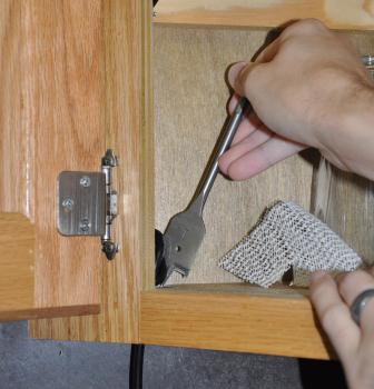
These hanging kits are designed to hold hanging planters which are pretty heavy and come with the parts to install on either a stud or directly into drywall.  The drywall anchor is a spring toggle bolt, which is capable of hanging a lot of weight. This is a bit overkill for this project, but it doesn’t hurt. For other projects, you may want to check out which kind of drywall anchor would be right for you. To install this toggle bolt, I used a half-inch spade drill bit to drill a hole in the ceiling large enough to accept the toggle bolt when it is folded.

Once the hole has been drilled, simply insert the toggle bolt and screw the hook until it is tight against the ceiling.

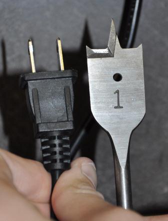
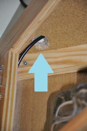
We planned to power the light using a power socket under the kitchen cabinets by the sink but we didn’t want the plug just hanging down from the ceiling for two reasons; 1) Because it is unsightly and 2) because the Hemma wire was several feet too long. What we decided to do was to run the wire inside our cabinets and leave the extra wire on top of the cabinet. To do this, we used a larger drill bit to drill a hole bottom shelf and the top of the cabinets as close to the back corner as possible.

A 1-inch spade drill bit which was just wide enough to handle the plug.

We threaded the wire through the holes and tied a knot just before the bottom hole leaving enough on the other side to reach the plug under the cabinets. This knot should prevent any extra wire from coming through the hole.

To keep the wire out of the way and tidy inside the cabinet, we used small nails to tack it to the back side of the cabinet facing. This also help rout the wire neatly around the inner shelves.

We got a shade from a local Habitat for Humanity ReStore for $2.00. These stores are great because they have a wide variety of random construction pieces and furniture for great prices and the money goes to help Habitat for Humanity. The particular share we got was a bit too big to fit on the screw part of the hemma, so I filed down some of the plastic on the hemma’s light socket to make some room. I was only able to thread a couple of threads on the socket with the screw piece, but that was plenty to hold the shade.

All in all, the IKEA Hemma proved to be a great solution for us. There are tons of really great examples out there using it as well. It allows you to be creative and still coming up with a professional look.  If you have used the Hemma for a DIY lighting project, we’d love to see what you did! Leave us a comment with info and a link.


A Simple Valentine’s Day Message

I wanted a simple but sweet Valentine to give out to my students.  I searched Pinterest and did not find anything that had the degree of simplicity I wanted.  That is when I decided to make my own.   I used the paint program that comes with Windows 7 and I was pleasantly surprised with the versatility and ease of use of this program.  I’ve had a thing for owls recently, so naturally I made my own owl graphic.

Read more

A Cheap but Quality Home Surveillance System

Today as I got into my car I realized that someone had broken into it and ransacked my glovebox and center console. I couldn’t nail down exactly when it happened but I couldn’t help but feel violated.  Someone else in my neighborhood also had a break in. I decided to do something about it. I immediately went to the closest store and grabbed a cheap webcam and prepared to make a motion triggered surveillance system. (Man, I love Linux).

Read more

First Weather Balloon Launch Video and Google Earth File (Pt. 2)

With the payload tested in a rocket, everything looked ready to go. I took it off the breadboard and built it onto a strip board PCB to make everything sturdy.

The next step was to create the payload box. The professor had done this before so he gave us tips on using foam core poster board, hot glue and HVAC tape. We chose to cover ours in mylar by applying a spray adhesive to the surface, then laying a sheet of mylar on it, and using credit cards to squeegee it flat as best as possible. The mylar was applied to the insides of the box before gluing, and the outside afterward.

Read more

First Weather Balloon Payload Testing on a Model Rocket (Pt.1)

Working with a professor at my college and Carolina Edge of Space in May of 2010 I, along with a small group of friends, sent a weather balloon 74,642 feet into the sky.  This post is mainly about the payload I designed, built and tested for the project.

This project was inspired by many seen recently online where students have been sending cheap payloads into the stratosphere. It started around December 2009 when we all met for the first time to discuss the project. It turns out that one of the professors in the Earth Sciences department focuses on remote sensing (gathering data about earth from satellites, etc.) who had done some weather balloon projects in the past. We all got together to discuss a possible launch.

Originally, the group included a lot of people, however, as time went on, fewer and fewer people showed up at the meetings or participated in the email conversations. There would be several payloads. Carolina Edge of Space would have a GPS tracking radio, the professor hosting this would carry two cameras in a payload with a HOBO data logger, one Grad student would build an “ash detector” and my group would build something to take a multitude of measurements.

First the payload sensor were picked out. Of course we wanted pictures. The professor provided us with Nikon Coolpix digital cameras and 2GD SD cards. These were chosen because they have a built in intervalometer and were very small. I tested the camera in my freezer (which gets down to -20 degrees Celsius (-40F) and usually got about 2 full hours of pictures every 30 seconds before the battery died. this was plenty as we expected about a 2 or 3 hour flight. Turning off the flash and increasing the time between pictures helped extend the life of the battery.

As for the custom payload, we wanted a barometer to see the change in air pressure, accelerometers to see how hard the payload would be whipped around in the winds, some ozone sensors and such to measure concentrations, a GPS so we would have a good clock as well Latitude, longitude and altitude. What seemed like a great custom embedded systems project turned into a simpler Arduino-based project as time and money became an issue.

I tried to get nice ozone sensors, however, everything was way too expensive and none of the companies I contacted were willing to donate to our cause. Then I remembered that I had seen some neat gas sensors at Futurlec, such as ozone sensors, and “air quality” (what ever that is…) that were quite cheap.  I grabbed a couple of each to play around with. I tested the Ozone sensor by placing it inside a bag with a running DC motor. The brushes of the DC motor arc as they move across the sections of the commutator and ionize the air. This effectively produces a bit of ozone (its that almost metallic smell DC motors or high voltage electronics give off.) The graph below shows the results of this test as raw ADC values from an arduino. Here you can download the raw ADC values and graph from this test in Open Document Spreadsheet format.

Ozone sensor test
Testing the Ozone Sensor

I also bought a few different barometric pressure sensors. The one I bought specifically for the weather balloon was hard to use as it was a differential and had to have a known pressure on one side to compare to. It also has two output pins which required an op-amp circuit to output the difference in pressure. Testing proved this was not the easiest sensor to use as I didn’t figure out the best way to seal off one side of the sensor. Instead I settled for a sensor that had a built-in vacuum on one side, and a single output pin, the MPXA6115A . This new pressure sensor would only go down to 15kPa (about 33,000ft I think) but I assumed that if we took external temperature as well, we could correlate it with the pressure up to a point, and when the senor stopped working, we could calculate the pressure based on the temperature data using a barometric formula.

Additionally, we wanted to use a GPS to get altitude data. I’ve been told that some GPS unit manufacturers limit the capabilities of their units to below 60,000 ft and a certain speed for safety reasons but I couldn’t find any info on that for my particular unit, the San Jose Navigation FV-M8 GSP module.

Acceleration was also something we wanted to measure. We used a Sparkfun ADXL300 3 axis accelerometer. Actually it had a 2 axis gyroscope built in as well, but we ran out of analog input pins on the Arduino and wanted to keep this as small and simple as possible, so we left those off.

All data was stored to a 2GB SD card.

I breadboarded the GPS, accelerometer, barometer, and gyroscope package and slapped together a simple SD card interface. The libraries I used were TinyGPS and fat16lib (for SD card use). Weather_Balloon_Code and schematic in case you’d like to build it yourself.

Weather Balloon Schematic
Schematic of the hardware

I flew this in a modified model rocket. I had two flights, one with an E-15-4 engine and the other with an E-30-4 engine. Here’s the Excel file of each of those two launches that show the values and plotted graphs of each flight.

First Flight Raw ADC data and graphs.

Second Flight raw ADC data and Graphs

I’m not sure which one used which engine. Here you can see a graph of the raw ADC pressure sensor values from one of the rocket launches. The air pressure decreases as the rocket altitude increases. You can see the wind and other affects from the rocket  sitting on the launch pad, then then drastic drop in pressure at the launch.  The ramp up on the end of the graph is when the rocket was floating back to the ground under a parachute. Calculations showed it went about 600ft I think.

Barometer_Test
Barometer data from Rocket test

To calculate the height the rocket went, we simply need to know a few little things about the set-up. (This gets a bit mathy, but not too bad). First, we knoow that the Arduino was set up to use a 5V ADC reference voltage, and it was set to do 10-bit conversions. Knowing that we can calculate the voltage that each raw ADC unit represents.

ADC Voltage / Max number the bits can represent

Formula 1

Formula 2


Multiply this by the lowest barometer reading we got (794 raw ADC units)

Formula 3

This is the voltage that the sensor was outputting. Now we look at the datasheet of the barometer (MPXA6115A) to find a conversion formula from volts to a measure of air pressure kPa.

Formula 4

Solve this for P since we already know the voltage:


Formula5


Now we can convert the kPa into a value we can use in an online Pressure to Altitude calculator such as inches of mercury. (1 kPa = 0.295333727 inches of mercury)


Formula 6

Now inserting this number into the online Pressure to Altitude calculator, we can get a rough altitude above sea level for the rocket, about 1280.6ft (390.3 meters).  This is above Sea-level, not the point that we launched. I happen to know that the height of the ground at the launch site is between 500-700ft  (150-215 meters).  So I subtract the average height (600ft) of the ground from the Altitude calculation I got previously to get:

1280ft – 600ft = Rocket height of about 680 feet.


*Formula graphics provided by this Online LaTeX Equation Editor.


Protected by CleanTalk Anti-Spam